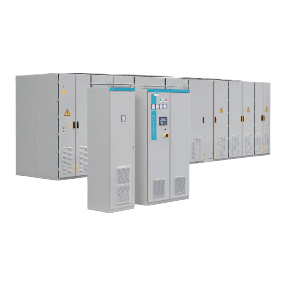
Siemens SINAMICS GL150 Referenzhandbuch - Seite 5
Blättern Sie online oder laden Sie pdf Referenzhandbuch für Industrielle Ausrüstung Siemens SINAMICS GL150 herunter. Siemens SINAMICS GL150 44 Seiten. Medium-voltage drive
Auch für Siemens SINAMICS GL150: Referenzhandbuch (38 seiten)

Table of contents
1
Introduction...................................................................................................................................................7
2
General scope of services ............................................................................................................................9
2.1
Routine test ............................................................................................................................11
2.2
Visual inspection ....................................................................................................................12
2.3
Function tests.........................................................................................................................13
2.4
Insulation test .........................................................................................................................14
2.5
Interface test ..........................................................................................................................15
3
Tests...........................................................................................................................................................17
3.1
Visual inspection ....................................................................................................................18
3.1.1
Rating plate ............................................................................................................................18
3.1.2
Housing degree of protection .................................................................................................18
3.1.3
Electrical cabinet components ...............................................................................................19
3.1.4
Cable installation....................................................................................................................19
3.1.5
Cable markings ......................................................................................................................20
3.1.6
Setting values of circuit breakers, if used...............................................................................20
3.1.7
Dimensions ............................................................................................................................20
3.2
Function test...........................................................................................................................22
3.2.1
Ready to start condition .........................................................................................................22
3.2.2
Excitation unit.........................................................................................................................22
3.2.3
Auxiliary voltages ...................................................................................................................22
3.2.4
Temperature monitoring in the control cabinet.......................................................................23
3.2.5
Redundant 230 V or 24 V auxiliary voltage supply ................................................................23
3.2.6
DC-link pulsed operation at 0 Hz ...........................................................................................24
3.2.7
DC-link pulsed operation at 2 Hz ...........................................................................................24
3.2.8
Line undervoltage...................................................................................................................25
3.2.9
Door limit switches .................................................................................................................25
3.2.10
Overcurrent limit.....................................................................................................................25
3.2.11
Ground fault monitoring..........................................................................................................26
3.2.12
Failure of actual value acquisition ..........................................................................................26
3.2.13
Missing input voltage..............................................................................................................27
3.2.14
Group alarm Power Stack Adapter ........................................................................................27
3.2.15
Group fault Power Stack Adapter...........................................................................................28
3.2.16
DriveCLiQ connection ............................................................................................................28
3.2.17
PROFIBUS connection with the excitation unit ......................................................................28
3.2.18
Failure of a power semiconductor module .............................................................................29
3.2.19
Safety shutdown.....................................................................................................................29
3.3
Cooling system test................................................................................................................30
3.3.1
Static pressure test ................................................................................................................30
3.3.2
Differential pressure measurement ........................................................................................31
3.3.3
Measuring the coolant conductivity and coolant temperature ................................................31
3.3.4
Leakage monitoring................................................................................................................32
SINAMICS GL150 6SL3855 F03 F70 F76 F79 F98 E11
Reference Manual Rev.201902141423 GL150 wassergekühlt
5
