Siemens SIPART PS2 Betriebsanleitung - Seite 19

Blättern Sie online oder laden Sie pdf Betriebsanleitung für Industrielle Ausrüstung Siemens SIPART PS2 herunter. Siemens SIPART PS2 28 Seiten. Mounting bracket kit
Auch für Siemens SIPART PS2: Installationsanweisung (4 seiten), Installationsanweisung (4 seiten), Hardware-Installationshandbuch (30 seiten), Technische Beschreibung (26 seiten), Kompakt-Bedienungsanleitung (35 seiten), Anleitung zur Installation des Kits (9 seiten), Installationsanweisung (11 seiten)
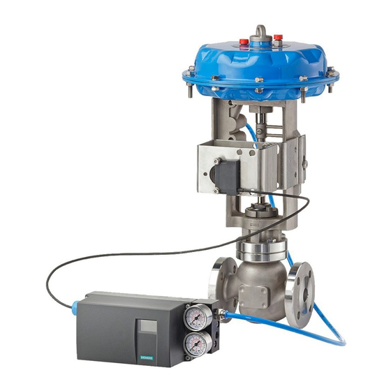
Siemens SIPART PS2 Betriebsanleitung
4.4

Connecting the mechanical limit switch module

Preparing to connect the mechanical limit switch module
NOTICE
Before you connect the mechanical limit switch module, observe the following conditions:
1. Only qualified personnel is permitted to connect the mechanical limit switch module.
2. Isolate all wires from power and make sure the device is truly isolated from power.
3. Construct the cross-sectional area of the connection cables in such a way that it is
4. Selected the wires on the basis of the following rule: The temperature at which the wires
5. Operate the Ex-version only in intrinsically safe circuits with approved switching
NOTICE
Prepare the cables or stranded wires as follows:
1. Insulate the cables in such a way that the insulation is flush with the terminal when
2. Fit ferrules to the ends of stranded wires.
Connecting the mechanical limit switch module
How to connect the mechanical limit switch module:
1. Loosen the screw ⑱ on the transparent cover ⑲.
2. Pull the transparent cover ⑲ to the front stop.
3. Tighten each cable in the corresponding terminal.
4. Push the transparent cover ⑲ to the stop of the motherboard.
5. Tighten the screw ⑱ on the transparent cover ⑲.
6. Attach the wires of each switch in pairs on the lug of the circuit board. Use the cable ties
SIPART PS2 with mechanical limit switch module
Operating Instructions (Compact), 04/2007, A5E01179056-01
appropriate for the permitted current load.
are permitted to be used must be 25°C above the maximum ambient temperature.
amplifiers.
plugging in the wires.
⑳ included with the delivery for this.
4.4 Connecting the mechanical limit switch module
Connecting
19