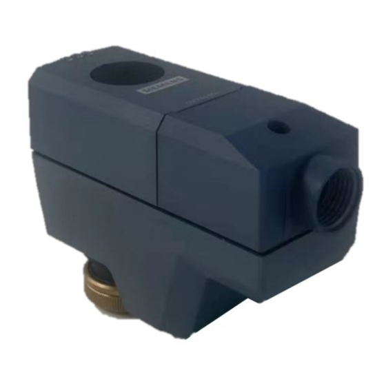
Siemens SSC161.05UT Handbuch - Seite 2
Blättern Sie online oder laden Sie pdf Handbuch für Controller Siemens SSC161.05UT herunter. Siemens SSC161.05UT 17 Seiten. Electromotoric actuator

Use
●
For zone valves VVP.., VXP.., VMP..: compatible with SSC161.05UT
●
For 2-/3-port valves: compatible with SSC161.05UT
●
Typically in chilled ceiling, VAV and fan coil unit applications
●
Max.10 units of SC161.05UT can operate in parallel, provided the controller output
suffices.
Technical design
When the actuator is driven by DC 0...10 V positioning signal, it produces a stroke, which is
transmitted to the valve stem.
DC 0...10 V positioning signal
●
The valve opens / closes in proportion to the
positioning signal at Y.
●
At DC 0 V, actuator stem is retracted, the normally
closed valve is fully closed.
●
When there is no operating voltage, the actuator
maintains its current position.
●
This actuator provides a DC 0...10 V position
feedback signal proportional to the stroke of the
actuator stem.
Y = Positioning signal Y [V]
H = Percentage of calibrated valve stroke
LED indication
Stroke movement: Stem retracting
Stroke movement: Stem extending
Type summary
Type
SSC161.05UT
2
Siemens
Smart Infrastructure
Status
Variants
Stem position
Calibration
Error
Manual operation
Stock number Operating
voltage
S55180-A149
AC/DC 24 V
LED indication patterns
SSC161.05UT
Flashing green in sequence: LED1-->LED2-->LED3 (500 ms each)
Flashing green in sequence: LED3-->LED2-->LED1 (500 ms each)
At H0 - H40: Constant green (LED3)
At H40 - H60: Constant green (LED2)
At H60 - H100: Constant green (LED1)
Flashing green (LED2): 100 ms on, 100 ms off
Constant red (LED2)
Flashing green/red alternatively (LED2): Green 500 ms, red 500 ms
Running
Running time
speed
5.5 mm
5 s/mm
27.5 s ± 25 %
Positioning
Actuator
signal
characteristic
DC 0...10 V
Linear
A6V13359035_en--_b
2023-05-16
