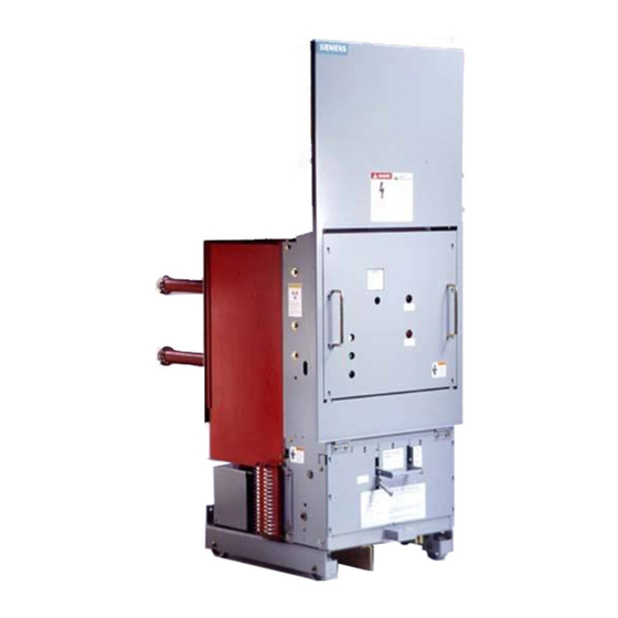
Siemens 15-FSV-1000 Installation, Betrieb und Wartung - Seite 21
Blättern Sie online oder laden Sie pdf Installation, Betrieb und Wartung für Schalter Siemens 15-FSV-1000 herunter. Siemens 15-FSV-1000 48 Seiten. Vacuum circuit breakers fsv series and msv series

Interrupter/Operator
Description
53
Close button
54
Tnp button
55
"Closing spring Charges"
indicator
58
Open-Close ind1cator
59
Operation counter
6 1 8
Shock Absorber
Closmg Spring
62
Charging Shaft
62 1
62. 2
Crank
Cam
62 3
62 5
Lever
62 5 1
Pawl roller
62 5 2
Pawl
63
Breaker Shaft
64
Tri p ping Spring
Tripping Spring
64 2
64 . 2
Pawl
64 3
Lever (lobes are omitted when
applied w1th screw type racking
64 3 1
Pawl roller
Figure 1 1
Operating Mechanism Open Position Closing Spring Charged and Latched
Closing (See Fig . 9, 1 0, 1 1 & 1 2)
If the b reaker is to be closed locally, the c losing spring is re
leased by p ressing CLOSE butto n , (53). In the case of remote
control and the spring release coil 52SRC, (53 . 1 ), u nlatches
the closing spri n g .
A s t h e closing spring discharges, t h e charging shaft, (62 . 1 ) ,
i s tu rned b y c rank, (62. 2). T h e c a m disc, ( 6 2 3 ) , a t t h e other
end of the charging s haft actuates the d rive lever, (62.6), with
the result that breaker shaft, (63), is tu rned by lever, (63 . 5 ) ,
v i a t h e trip free coupling rod , (62.8) . At t h e same time , the
levers, (63 1 ) , (63 . 5 ) and (63 7) fixed on the breaker shaft
operate the three insulated couplers for the b reaker poles.
Lever, (63 . 7) , changes the open-c lose indicator over to open
Lever, (63 . 5 ) , charges the tripping spring, (64 ) , d u ring closing ,
and the b reaker is latched in the closed position by lever,
(64 . 3 ) , with pawl roller, (64 . 3. 1 ) , and by pawl, (64 2). Lever,
(63.1 ), actuates the auxiliary switch , through the linkage, (68 . 1 )
The crank, (62.2), on the c harging shaft moves the linkage,
(55 . 1 ) , by acting on the cont rol lever, (55 .2) The "Closing
spring charged" indication is thus cancelled and, the limit
switches, (50. 4), switch i n the control s u p ply to cause the
closing spring to recharge immediately.
62 1
62
55
58
59
6 1 8
Trip Free Operation
The trip free coupling rod , (62.8) permits the immediate de
coupling of the d rive leve r
override closing action by trip command or by means of the
racking interlocks.
The trip free coupling rod (62 8) forms a link between the d rive
lever (62 . 6) and b reaker shaft (63). The rig idity of this link
depends u pon a spring retu rn latch carried within the cou pling
rod . The latch is pivotable within the coup ling rod and
mally positioned to ensure the couplers rigid ity. Trip F ree Cou
pling Link (62 8 2) and Trip Free Coupling lever (62.8.3) cause
the spring retu rn latch position to be dependent u pon the
breakers normal tripping components and the breaker 's rack
ing interlock. Thu s , whenever a trip command is applied or
the breaker is not in the fully "connected" or test position, the
trip free coupling rod is no longer rigid , effectively decoupling
the d rive lever and b reaker shaft. Under these conditions the
breaker main contacts can not be closed.
64
64 3
63
(62 .6)
and breaker shaft, (63) to
Page 1 6
I S
nor
