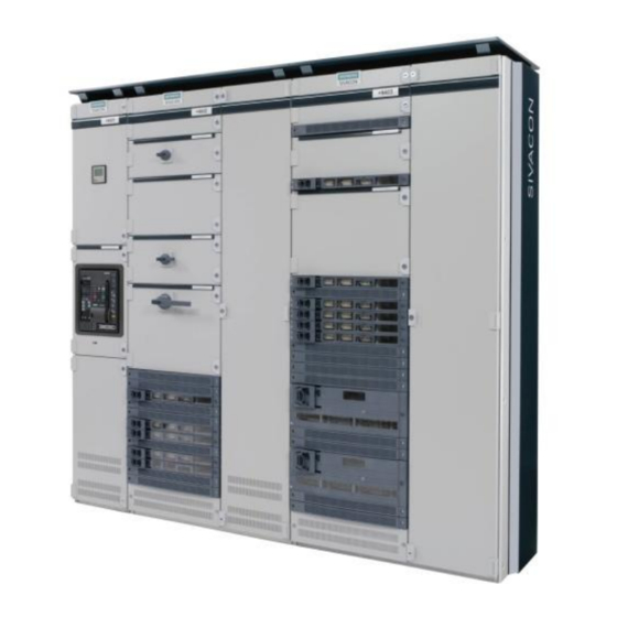
Siemens SIVACON S 8PQ Series Betriebsanleitung - Seite 26
Blättern Sie online oder laden Sie pdf Betriebsanleitung für Schalter Siemens SIVACON S 8PQ Series herunter. Siemens SIVACON S 8PQ Series 40 Seiten. Design-verified low-voltage switchboard
Auch für Siemens SIVACON S 8PQ Series: Betriebsanleitung (11 seiten)

- 1. Table of Contents
- 2. Sivacon Bauartgeprüfte Niederspannungsschaltanlage S8 - Felder mit Abzweigen in Einschubtechnik Design-Verified Low-Voltage Switchboard S8- Cubicles with Feeders in Withdrawable Design Betriebsanleitung / Operating Instructions Bestell-Nr. / Order No.: 8P
- 3. Description of the MCC Cubicle
- 4. Electrical Connections
3.2.2 Einschübe aus der Betriebsstellung in die Trennstellung
bringen
Warnung
Das Betätigen der Einschübe darf nur bei geschlos-
sener Fachtür erfolgen
Warnung
Befindet sich der Einschub in der Betriebsstellung
liegt auch bei ausgeschaltetem Hauptschalter
einseitig Spannung an
Hauptschalter ausschalten (Stellung 0)
Schieber (1) vor der Betätigungsöffnung nach rechts öffnen (ist
nur bei ausgeschaltetem Hauptschalter möglich)
Das große Betätigungswerkzeug für „Betrieb" mit der langen
Nase nach links zeigend in die Betätigungsöffnung einstecken.
Das Betätigungswerkzeug bis zum Anschlag hineindrücken und
im gedrücktem Zustand gegen den Uhrzeigersinn 180° bis
zum Anschlag drehen und das Werkzeug herausziehen. Die
Stellungsanzeige (4) zeigt ein grünes Feld mit „0" an.
Achtung
Wird das Betätigungswerkzeug für „Betrieb" nicht
hineingedrückt, ist keine Drehung möglich bzw. bei
Gewaltanwendung kann die Funktion beeinträch-
tigt werden.
3.2.3
Einschübe aus der Trennstellung in die Teststellung
bringen
Warnung
Das Betätigen der Einschübe darf nur bei ge-
schlossener Fachtür erfolgen
Fachtür verschließen
Schieber (1) vor der Betätigungsöffnung nach rechts öffnen
Das kleine Betätigungswerkzeug für die Teststellung mit der
Nase nach rechts zeigend in die Betätigungsöffnung einste-
cken. Das Betätigungswerkzeug im Uhrzeigersinn 180° bis zum
Anschlag drehen und das Werkzeug herausziehen. Die Stel-
lungsanzeige (4) zeigt ein blaues Feld mit „TEST" an.
3.2.4 Einschübe aus der Teststellung in die Trennstellung
bringen
Warnung
Das Betätigen der Einschübe darf nur bei geschlos-
sener Fachtür erfolgen
Schieber (1) vor der Betätigungsöffnung nach rechts öffnen.
Das kleine Betätigungswerkzeug für die Teststellung mit der
Nase nach links zeigend in die Betätigungsöffnung einstecken.
Das Betätigungswerkzeug entgegen dem Uhrzeigersinn 180°
bis zum Anschlag drehen und das Werkzeug herausziehen. Die
Stellungsanzeige (4) zeigt ein grünes Feld mit „0" an.
24
3.2.2 Setting withdrawable units from the connected to discon-
nected position
Warning
Operating the withdrawable units is only permitted
when the compartment door is closed
Warning
If the withdrawable unit is in the connected position,
voltage is also present even if the main switch is
switched off.
Switch off the main switch (position 0)
Open the gate valve (1) in front of the actuating opening to the
right (is only possible, when main switch is switched off)
Insert the actuating tool for "operation", with the long nib pointing
to the left, into the actuating opening. Push in the actuating tool
as far as it will go (see figure below) and move it 180° counter-
clockwise in the pressed state until the stop and take out the
tool. The position (4) shows a green area with "0".
Warning
If the actuating tool for "operation" is not pressed
in, no turning is possible or the function can be
impaired by using force.
3.2.3 Setting withdrawable units from the disconnected to the
test position
Warning
Operating the withdrawable units is only permitted
when the compartment door is closed.
Lock the compartment door
Open the gate valve (1) in front of the actuating opening to the
right.
Insert the small actuating tool, with the long nib pointing to the
right, into the actuating opening. Move the actuating tool 180°
clockwise up to the stop and take out the tool. The position dis-
play (4) shows a blue area with "TEST".
3.2.4 Setting withdrawable units from test to the disconnected
position
Warning
Operating the withdrawable units is only permitted
when the compartment door is closed.
Open the gate valve (1) in front of the actuating opening to the
right.
Insert the small actuating tool for the test position, with the nib
pointing to the left, into the actuating opening. Move the actuat-
ing tool 180° counterclockwise up to the stop and take out the
tool. The position display (4) shows a green area with "0".
8PQ9800-3AA48
