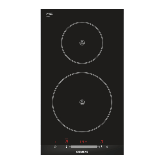
Siemens EH375ME11E/21 Installationsanleitung Handbuch - Seite 4
Blättern Sie online oder laden Sie pdf Installationsanleitung Handbuch für Kochfeld Siemens EH375ME11E/21 herunter. Siemens EH375ME11E/21 14 Seiten.

Vorbereitung der Einbaumöbel, Abb. 1/2/3
Einbaumöbel: Sie müssen bis mindestens 90 °C temperaturbe-
ständig sein.
Ausschnitt: Späne nach den Ausschnittarbeiten entfernen.
Schnittflächen: Mit hitzebeständigem Material versiegeln.
Einbau über einem Schubfach, Abbildung 2a
Im Schubfach befindliche Metallgegenstände können durch den
Rückstrom der Luft, bei der Belüftung des Kochfelds hohe Tem-
peraturen erreichen. Daher wird empfohlen einen Zwischenbo-
den einzubauen.
Zwischenboden: Ein geeignetes Zubehörteil kann über unseren
Kundendienst bezogen werden. Die Artikelnummer für dieses
Zubehörteil lautet 448964.
Arbeitsplatte: Sie muss mindestens 20 mm dick sein.
Der Abstand zwischen dem oberen Bereich der Arbeitsplatte
und dem oberen Bereich des Schubfachs muss 65 mm betra-
gen.
Montage über einem Backofen, Abbildung 2b
Ablage: Muss über eine Mindestdicke von 30 mm verfügen.
Hinweis: Schlagen Sie in der Montageanleitung für den Backo-
fen nach, falls der Abstand zwischen Kochfeld und Backofen
vergrößert werden muss.
Belüftung: Der Abstand zwischen Backofen und Kochfeld muss
mindestens 5 mm betragen.
Einbau über dem Geschirrspüler
Es muss ein Zubehörteil dazwischen eingebaut werden. Zube-
hörteile erhalten Sie bei unserem Kundendienst. Die Artikelnum-
mer für dieses Zubehörteil lautet 448964.
Arbeitsplatte: Sie muss mindestens 20 mm und darf höchstens
40 mm dick sein.
Es muss folgender Abstand zwischen dem oberen Bereich der
Arbeitsplatte und dem oberen Bereich des Geschirrspülers ein-
gehalten werden:
60 mm bei Einbau über einem Kompakt-Geschirrspüler.
■
65 mm bei Einbau über einem normalen Geschirrspüler.
■
Gebläse, Abbildung 3
Für die Lüftung des Kochfelds ist Folgendes notwendig:
Eine Öffnung im oberen Bereich der Rückwand des Möbels
■
(Abb. 3a).
Ein Abstand zwischen der Rückwand des Möbels und der
■
Küchenwand (Abb. 3b).
Einbau des Geräts, Abb. 4/5
Hinweis: Zum Einbauen des Kochfeldes Schutzhandschuhe ver-
wenden. Die nicht sichtbaren Flächen können scharfe Kanten
aufweisen.
Die mitgelieferten Verankerungen einbauen (Abb. 4).
1.
Hinweis: Keine elektrischen Schraubendreher verwenden.
Das Gerät ans Stromnetz anschließen und auf ordnungsge-
2.
mäßen Betrieb überprüfen.
– Hinweise zur elektrischen Spannung siehe Typenschild.
– Nur nach dem Anschlussplan anschließen (Abb. 5).
1. Braun
2. Blau
3. Gelb und grün
Hinweis: Je nach Anschlussart muss eventuell die Anordnung
der vom Werk gelieferten Klemmen verändert werden.
Ausbau des Geräts
Das Gerät von der Stromzufuhr trennen.
Die Halterungen entfernen.
Entnehmen Sie das Kochfeld, indem Sie von unten dagegen
drücken.
Achtung!
Schäden am Gerät! Versuchen Sie nicht, das Gerät durch
Hebeln von oben zu entnehmen.
en
Ú
Installation instructions
Important notes
Safety: Safety in use is only guaranteed if the technical
installation of the hob has been carried out correctly and in
accordance with the assembly instructions. The installation
technician shall be liable for any damage caused as a result of
unsuitable installation.
Electric connection: Only by an authorised specialist
technician. The guidelines set out by the local electricity provider
must be observed.
Type of connection: The appliance falls under protection class I
and can only be used in combination with a grounding
conductor connection.
The manufacturer accepts no responsibility for any malfunction
or damage caused by incorrect electrical installations.
Installation: The appliance must be connected to a fixed
installation and the means of disconnecting it from the fixed
installation must be installed according to the installation
instructions.
Built-in assembly under worktop: The induction hobs may only
be installed over a drawer, ovens with forced ventilation from the
same brand and dishwashers from the same brand.
Refrigerators, unventilated ovens and washing machines may
not be installed beneath the hob.
Power cable: Do not tie the power cable or pass it along sharp
edges. If there is an oven installed below, pass the cable along
the rear corners of the oven to the connection box. It must be
positioned so that it does not touch any of the hot parts of the
hob or the oven.
Hob: flat, horizontal, stable. Follow the hob manufacturer's
instructions.
Warranty: an unsuitable installation, connection or assembly will
invalidate the product warranty.
Note: Any change to the appliance's interior, including changing
the power cable, must only be performed by specially trained
members of the Technical Assistance Service.
Preparation of assembly units, figures 1/2/3
Built-in kitchen units: Minimum temperature resistance of
90°C.
Gap: Remove any shavings after performing cutting work.
Cut surfaces: Seal with heat resistant material.
Assembly over drawer, figure 2a
Metal objects stored inside the drawer could become very hot
due to the air recirculating from the hob ventilation system. If
this occurs, an intermediate support is recommended.
Intermediate support: An appropriate accessory can be
obtained from our Technical Assistance Service. The reference
code for this accessory is 448964.
Worktop: Must have a minimum thickness of 20 mm.
The distance between the top of the working surface and the top
of the drawer must be 65 mm.
Assembly over oven, figure 2b
Hob: must have a minimum thickness of 30 mm.
Note: If the distance between the hob and oven must be
increased, refer to the installation instructions for the oven.
Ventilation: The distance between the oven and the hob must be
at least 5 mm.
Installation above the dishwasher
An intermediate accessory must be installed. The accessory
may be ordered from our Technical Assistance Service. The
reference code for this accessory is 448964.
Worktop: Must have a minimum thickness of 20 mm and
maximum thickness of 40 mm.
The space between the top of the working surface and the top
of the dishwasher must be:
60 mm if installed over a compact dishwasher.
■
65 mm if installed over a full-size dishwasher.
■
Ventilation, figure 3
Ventilating the hob requires:
an opening on the upper part of the kitchen unit's rear wall
■
(figure 3a).
a separation between the rear part of the kitchen unit and
■
kitchen wall (figure 3b).
