Cisco ASA 5506W-X Montieren Sie das Fahrgestell - Seite 3

Blättern Sie online oder laden Sie pdf Montieren Sie das Fahrgestell für Drahtloser Zugangspunkt Cisco ASA 5506W-X herunter. Cisco ASA 5506W-X 10 Seiten. Threat defense reimage guide
Auch für Cisco ASA 5506W-X: Schnellstart-Handbuch (10 seiten), Konfigurationshandbuch (13 seiten), Schnellstart-Handbuch (14 seiten), Handbuch zur einfachen Einrichtung (11 seiten), Software-Handbuch (37 seiten), Montieren und anschließen (12 seiten), Installationshandbuch (46 seiten)
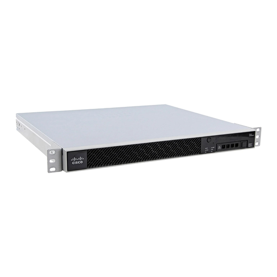
Cisco ASA 5506W-X Montieren Sie das Fahrgestell
Mount the Chassis
You can only mount the chassis with the front panel oriented toward either the ceiling or the floor. Wall mounting in
other orientation is not supported.
What to do next
Install the cables as described in

Rack-Mount the Chassis

The rack-shelf kit (part number 800-107605-01) contains the following items:
Note
There are two sets of four screws that you can use to secure the chassis to your rack. Chose the screws that
fit your rack.
• Rack shelf (part number 700-122662-01)
• Sliding rack tray (part number 800-107648-01)
• Two cable guides (part number 700-122664-01)
• Six Phillips M3 x 0.5 x 10 mm screws (part number 48-0796-01); use these screws to install the cable
• Six Phillips M3 x 6 mm screws (part number 48-0384-01); use these screws to secure the rack shelf onto
• Four Phillips 12-24 x 0.75 inch screws (part number 48-0440-01); use these screws to secure the
• Four Phillips 10-32 x 0.75 inch screws (part number 48-0441-01); use these screws to secure the
Note
You mount only one ASA 5506H-X in the rack-mount shelf.
The dimensions of the ASA 5506H-X are 3.46 x 18.3 x 19.5 inches (8.79 x 46.48 x 49.52 cm). The PID is
asa5506h-rack-mnt=.
Step 1
Install the cable guides on the sliding rack tray:
guides.
the chassis.
sliding-rack tray to your rack.
Quick Start Guide
for your default software configuration.
Rack-Mount the Chassis
Mount the Chassis
3