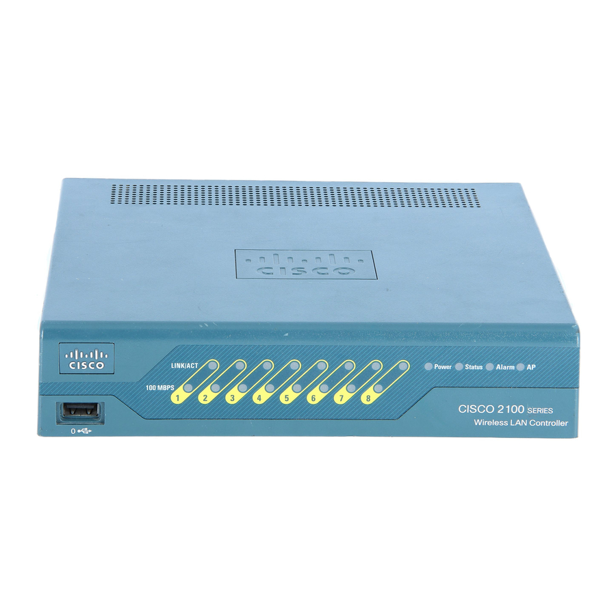
Cisco 5500 Series Handbuch - Seite 9
Blättern Sie online oder laden Sie pdf Handbuch für Netzwerk-Hardware Cisco 5500 Series herunter. Cisco 5500 Series 19 Seiten. Cisco 8500 series
wireless lan controller
Auch für Cisco 5500 Series: Konfigurationshandbuch (40 seiten), Installationshandbuch (34 seiten), Konfigurationshandbuch (50 seiten)

Chapter 7
Maintaining the Cisco Catalyst 5500 Multiswitch Router
Removing an AC-Input Power Supply
Follow these steps to remove an AC-input power supply:
In systems with redundant power supplies, the faulty supply can be replaced while the system is
Note
operating.
Turn off the power switch on the power supply you are removing (see
Step 1
Warning
Do not touch the power supply when the power cord is connected. For systems with a power switch,
line voltages are present within the power supply even when the power switch is off and the power
cord is connected. For systems without a power switch, line voltages are present within the power
supply when the power cord is connected.
Failure to turn off the power supply could result in equipment damage.
Caution
Figure 7-7
Metal prongs
Step 2
Disconnect the power cord from the power source.
Before working on a chassis or working near power supplies, unplug the power cord on AC units;
Warning
disconnect the power at the circuit breaker on DC units.
Disconnect the power cord from the power supply being removed.
Step 3
Using a flat-blade screwdriver, loosen and remove the captive installation screws (see
Step 4
Caution
Use both hands to install and remove power supplies.
Step 5
Grasp the power supply handle with one hand and place your other hand underneath to support the
bottom of the supply, as shown in
OL-0542-06
AC-Input Power Supply Front Panels
Power connection
AC
FAN
OUT PUT
OK
OK
FAIL
o
Power switch
Captive screw
Figure 7-8
Cisco MGC Software Release 7 Operations, Maintenance, and Troubleshooting Guide
Figure
(Cisco Catalyst 5000 supply shown).
Replacing Hardware Components
7-7).
Figure
7-7).
7-9
