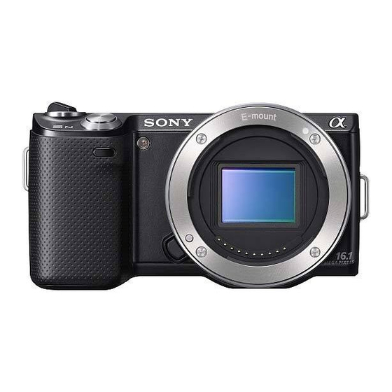
Sony NEX-5K - alpha; Nex-5 With 18-55mm Lens Wartungshandbuch - Seite 8
Blättern Sie online oder laden Sie pdf Wartungshandbuch für Digitalkamera Sony NEX-5K - alpha; Nex-5 With 18-55mm Lens herunter. Sony NEX-5K - alpha; Nex-5 With 18-55mm Lens 34 Seiten. Interchangeable lens digital camera
Auch für Sony NEX-5K - alpha; Nex-5 With 18-55mm Lens: 3D-Anweisungen (9 seiten), Funktion Handbuch (7 seiten), Service-Handbuch (49 seiten)

Ver.1.2 2010.07
The changed portions from
Ver.1.1 are shown in blue.
2-1. EXPLODED VIEWS
2-1-1. OVERALL SECTION
(NEX-5A/5D/5K/5CK/5H)
ns: not supplied
1(Claw)
1-2
LCD Section
(See Page 2-4)
1-1
Note3: Refer to "THE COMBINATION OF CABINET'S COLOR AND
SCREW (NEX-5A/5D/5K/5CK/5H)" on page 2-1 about the
combination of cabinet's color and screw.
Note4: Refer to "Assembly-6: Method of attachment of BT Lid Assy"
when you assemble.
Ref. No.
Part No.
Description
1
X-2547-947-2
LID ASSY (BLACK), BT (BLACK)
1
X-2547-948-2
LID ASSY (SILVER), BT (SILVER)
* 2
4-191-980-01
LABEL, MS
3
4-186-475-01
SPRING, BT LID OPEN (Note4)
4
X-2547-945-1
CABINET (REAR) ASSY (BRACK) (BLACK) (Note1, 2)
4
X-2547-946-1
CABINET (REAR) ASSY (SILVER) (SILVER) (Note1, 2)
5
4-186-478-01
GRIP (REAR), BLACK (BLACK)
5
4-186-478-11
GRIP (REAR), SILVER (SILVER)
6
4-186-479-01
SHEET, GRIP (REAR) ADHESIVE
7
4-186-476-01
SHAFT, BT LID
NEX-3A/3D/3K/5A/5D/5K/5CK/5H_L2
A6CCCE74558B3E905AD2CEF677F08944E4F80AE9D638E1A7EC0B95815DA1F3ED
#200
#202
(Note3)
2�
8
7
2(Claw)
(Note3)
#196
#201
#155
3
#200
(Note4)
#202
(Note3)
1
Note3: キャビネット色とネジの組合わせについては,2 - 1 ページ
の "THE COMBINATION OF CABINET' S COLOR AND SCREW
(NEX-5A/5D/5K/5CK/5H)" を参照してください。
Note4: 組立時は "Assembly-6: Method of attachment of BT Lid Assy"
を参照してください。
Ref. No.
Part No.
Description
8
1-487-968-12
SWITCH BLOCK, CONTROL (BLACK)
8
1-487-968-22
SWITCH BLOCK, CONTROL (SILVER)
* 9
4-186-841-01
LABEL, VCCI/ JAPAN RECYCLE MARK (J)
#155
3-080-204-31
SCREW, TAPPING, P2
#196
4-178-124-01
SPECIAL (M1.4 (D2.75)) (BLACK) (Note3)
#200
4-178-124-11
SPECIAL (M1.4 (D2.75)) (BLACK) (Note3)
#201
4-178-124-21
SPECIAL (M1.4 (D2.75)) (SILVER) (Note3)
#202
4-178-124-31
SPECIAL (M1.4 (D2.75)) (SILVER) (Note3)
DISASSEMBLY
1. Remove to numerical order (
#200 / #202 X 4 → USB Cover Open (1-1) → #155 X 1 → Shoe Cover Open (1-2) →
1
#196 / #201 X 1 →LCD Panel Open
Left View
Screw
#155:
M1.7 X 6.0 (Tapping)
(Black)
3-080-204-31
6
1.7
5
6.0
ns
Note
1�
4
Note1: Perform the following procedures to remove Cabinet (Rear)
(Note1, 2)
Assy.
(1) Open LCD at the angle shown below.
9
(2) Raise the lower part of Cabinet (Rear) Assy, and slide it
upward.
2
(3) Remove Cabinet (Rear) Assy while turning it in the
direction indicated by arrows.
Note2: Refer to "Assembly-1: Method of attachment of Cabinet (Rear)
Assy" when you assemble.
2-3
1
to
2
) in the left figure.
Bottom View
Right View
#200
#202
#200
#202
#196: M1.4 X 2.0
#200: M1.4 X 3.8
#201: M1.4 X 2.0
(Black)
(Black)
4-178-124-01
4-178-124-11
1.4
1.4
2.0
3.8
Note1: 後キャビネットAssyを取り外す場合,以下の手順で行ってく
(1) LCDを下図の角度に開きます。
(2) 後キャビネットAssyの下部を手前へ起こし,後キャビ
(3) 後キャビネットAssyを矢印の方向に回転させながら,
Note2: 組立時は "Assembly-1: Method of attachment of Cabinet
Top View
#155
#196
#201
#202: M1.4 X 3.8
(Silver)
(Silver)
4-178-124-21
4-178-124-31
1.4
1.4
3.8
2.0
ださい。
ネットAssyを上部へスライドします。
取り外します。
(Rear) Assy" を参照してください。
