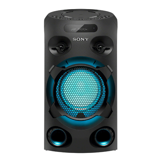
Sony ZS-RS80BT Service-Handbuch - Seite 24
Blättern Sie online oder laden Sie pdf Service-Handbuch für Stereo System Sony ZS-RS80BT herunter. Sony ZS-RS80BT 38 Seiten.

2019/02/28 22:48:45 (GMT+09:00)
MHC-V02
• Note for Printed Wiring Boards and Schematic Diagrams
Note on Printed Wiring Board:
• X : parts extracted from the component side.
•
: parts extracted from the conductor side.
•
: Pattern from the side which enables seeing.
(The other layer's patterns are not indicated.)
Caution:
Pattern face side:
Parts on the pattern face side seen
(Conductor Side)
from the pattern face are indicated.
Parts face side:
Parts on the parts face side seen from
(Component Side)
the parts face are indicated.
• MOTHERBOARD board is multi-layer printed board. However,
the patterns of intermediate layers have not been included in
diagrams.
Indication of transistor
C
Q
These are omitted.
B
E
D
Q
These are omitted.
G
S
Q
B
C E
These are omitted.
Q
B
C
E
These are omitted.
Note : When the MOTHERBOARD mounted pc board
is replaced, be sure to refer to "DESTINATION
SETTING METHOD" and "NOTE OF REPLACING
THE MOTHERBOARD MOUNTED PC BOARD" on
page 5.
MHC-V02
Note on Schematic Diagram:
• All capacitors are in μF unless otherwise noted. (p: pF)
50 V or less are not indicated except for electrolytics
and tantalums.
• All resistors are in and
1
/
W or less unless otherwise
4
specifi ed.
•
: Internal component.
f
• 2 : Nonfl ammable resistor.
• 5 : Fusible resistor.
• C : Panel designation.
Note: The components identifi ed by mark 0 or
dotted line with mark 0 are critical for safety.
Replace only with part number specifi ed.
Note: Les composants identifi és par une marque
sont critiques pour la sécurité.
0
Ne les remplacer que par une pièce portant
le numéro spécifi é.
• A : B+ Line.
• B : B– Line.
• H : Adjustment for repair.
• Voltages and waveforms are dc with respect to ground under
no-signal (detuned) conditions.
no mark : TUNER
(
) : CD PLAY
{
} : DVD PLAY
[
] : USB
<
> : Bluetooth
: Impossible to measure
*
• Voltages are taken with VOM (Input impedance 10 M).
Voltage variations may be noted due to normal production
tolerances.
• Waveforms are taken with a oscilloscope.
Voltage variations may be noted due to normal production
tolerances.
• Circled numbers refer to waveforms.
• Signal path.
: AUDIO
F
f
: TUNER (FM)
d
: USB
: AUDIO DIGITAL
J
N
: MIC
• Circuit Boards Location
PANEL board
VFD_IR board
SPK LED board
24
24
SMPS board
MOTHERBOARD board
SYS SET
