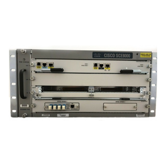
Cisco SCE8000 GBE Installation von - Seite 11
Blättern Sie online oder laden Sie pdf Installation von für Netzwerk-Hardware Cisco SCE8000 GBE herunter. Cisco SCE8000 GBE 21 Seiten. 10gbe platform
Auch für Cisco SCE8000 GBE: Schnellstart-Handbuch (25 seiten), Konfigurationshandbuch (18 seiten), Verfahren zum Entfernen und Ersetzen (36 seiten)

Chapter 4 Installing the Cisco SCE8000 Chassis
Figure 4-11
Figure 4-12
IEC 60320 C20
DC-Powered Systems
Basic guidelines for DC-powered systems include the following:
•
•
•
•
•
Do not connect the DC-return wire to the system frame or to the system grounding equipment.
Caution
OL-21054-04
CAB-AC-16A-AUS
Plug: AU20S3
CAB-C19-CBN
Connector:
Cordset rating: 16 A, 250 V
Each chassis power supply should have its own dedicated input power source. The source must
comply with the safety extra-low voltage (SELV) requirements in the UL 60950, CSA 60950, EN
60950, and IEC 60950 standards.
The DC supplies each have the provision for a dual connection to the power source in order to permit
high-power operation without exceeding current ratings. For the SCE8000, it is not necessary to
connect both of these inputs to DC power sources; it is sufficient to connect only the '1' connections.
Each circuit must be protected by a dedicated two-pole circuit breaker. The circuit breaker should
be sized according to the power supply input rating and local or national code requirements.
The circuit breaker is considered the disconnect device and should be easily accessible.
The system ground is the power supply and chassis ground.
Cordset rating: 16 A, 250 V
Length: 14 ft 0 in. (4.26 m)
Length: 9 ft 0 in. (2.7 m)
Cisco SCE8000 10GBE Installation and Configuration Guide
DC-Powered Systems
Connector: IEC 60320 C19
Connector:
IEC 60320 C19
4-11
