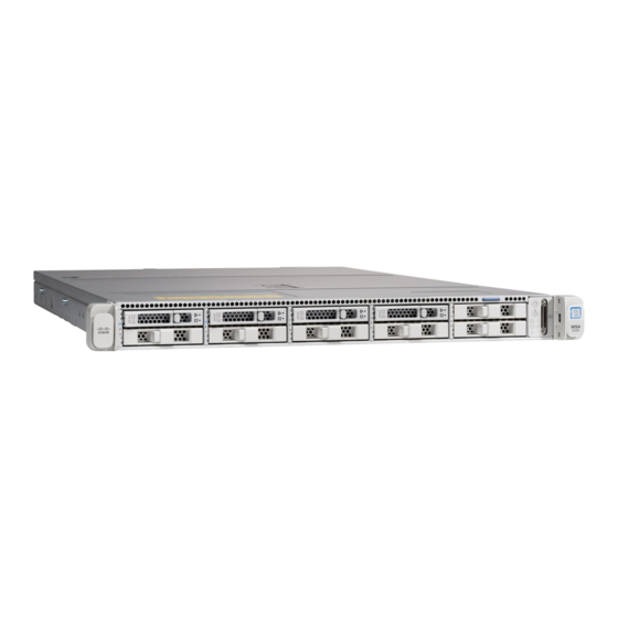
Cisco S695F Handbuch - Seite 12
Blättern Sie online oder laden Sie pdf Handbuch für Server Cisco S695F herunter. Cisco S695F 24 Seiten. Web security appliance
Auch für Cisco S695F: Handbuch "Erste Schritte (18 seiten), Hardware-Installationshandbuch (50 seiten)

Rear Panel
The following figure shows the rear panel of the WSA S695. See
of the LEDs.
Figure 11: S695 Rear Panel
1
Proxy port 1 (P1)
Connects to the network for both incoming and
outgoing traffic.
3
Traffic monitor port 1 (T1)
Use for Duplex Ethernet tap; one cable for all
incoming and outgoing traffic.
5
1050-W AC power supply (PSU 1)
7
Threaded holes for dual-hole grounding lug
Use is optional. The supported AC power supplies
have internal grounding, so no additional chassis
grounding is required.
9
USB 3.0 Type A (USB 2)
11
Management interface 2 (MGMT 2)
Not in use
13
Serial console port (Console)
RJ-45 connector that directly connects a
management computer to the appliance.
Overview
12
Rear Panel LEDs, on page 14
2
Proxy port 2 (P2)
When P1 and P2 are both enabled, you must
connect P1 to the internal network and P2 to the
internet.
Note
You can connect P1 and P2 to an L4
switch, WCCP router, or network
switch.
4
Traffic monitor port 2 (T2)
Use for Simplex Ethernet tap; one cable connected
to T1 for all packets going to the internet. and one
cable connected to T2 for all packets coming from
the internet.
6
1050-W AC power supply (PSU 2)
8
USB 3.0 Type A (USB 1)
10
Management interface 1 (MGMT 1)
Restricted to management use only
12
RPC port (RPC)
Use for remote power cycling.
14
Unit identification button
Overview
for a description
