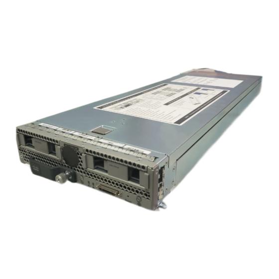
Cisco SNS-3595-K9 Installationshandbuch - Seite 28
Blättern Sie online oder laden Sie pdf Installationshandbuch für Server Cisco SNS-3595-K9 herunter. Cisco SNS-3595-K9 36 Seiten.
Auch für Cisco SNS-3595-K9: Installation der Software (38 seiten)

Local Connection Procedure
• The NIC redundancy is active-active.
• DHCP is enabled.
• IPv4 is enabled.
You can connect to the system using two methods:
• Local setup—Use this procedure if you want to connect a keyboard and monitor to the system for setup.
• Remote setup—Use this procedure if you want to perform setup through your dedicated management
Note
To configure the system remotely, you must have a DHCP server on the same network as the system. Your
DHCP server must be preconfigured with the range of MAC addresses for this server node. The MAC address
is printed on a label on the rear of the server node. This server node has a range of six MAC addresses assigned
to the Cisco IMC. The MAC address printed on the label is the beginning of the range of six contiguous MAC
addresses.
Local Connection Procedure
Step 1
Attach a power cord to each power supply unit in your server, and then attach each power cord to a grounded AC power
outlet. See
Power Specifications, on page 14
Wait for approximately two minutes to let the server boot in standby power during the first bootup.
You can verify system power status by looking at the system Power Status LED on the front panel (see
on Cisco SNS 3515 and 3595 Appliances, on page
Step 2
Connect a USB keyboard and VGA monitor to the server using one of the following methods:
• Connect a USB keyboard and VGA monitor to the corresponding connectors on the rear panel (see
or SNS 3595 Appliance Back Panel View, on page
• Connect an optional KVM cable (Cisco PID N20-BKVM) to the KVM connector on the front panel (see
SNS-3515 or 3595 Appliance Front Panel View, on page 2
and VGA monitor to the KVM cable.
Step 3
Open the Cisco IMC Configuration Utility:
a) Press and hold the front panel power button for four seconds to boot the server.
b) During bootup, press F8 when prompted to open the Cisco IMC Configuration Utility.
This utility has two windows that you can switch between by pressing F1 or F2.
Cisco Secure Network Server 3500 Series Appliance Hardware Installation Guide
24
Shared LOM EXT mode enables the 1-Gb Ethernet ports and the ports on any installed Cisco virtual
interface card (VIC) to access Cisco Integrated Management Interface (Cisco IMC). If you want to use
the 10/100/1000 dedicated management ports to access Cisco IMC, you can connect to the server and
change the NIC mode as described in Step 1 of the procedures given below.
All Ethernet ports are utilized simultaneously.
This procedure can use a KVM cable (Cisco PID N20-BKVM) or the ports on the rear of the server. See
Local Connection Procedure, on page
LAN. See
Remote Connection Procedure, on page
Install the Cisco SNS 3515 and Cisco SNS 3595 Hardware Appliances
24.
25.
for power specifications.
1). The system is in standby power mode when the LED is amber.
5).
for the connector location). Connect your USB keyboard
LED Indicators
Cisco SNS 3515
Cisco
