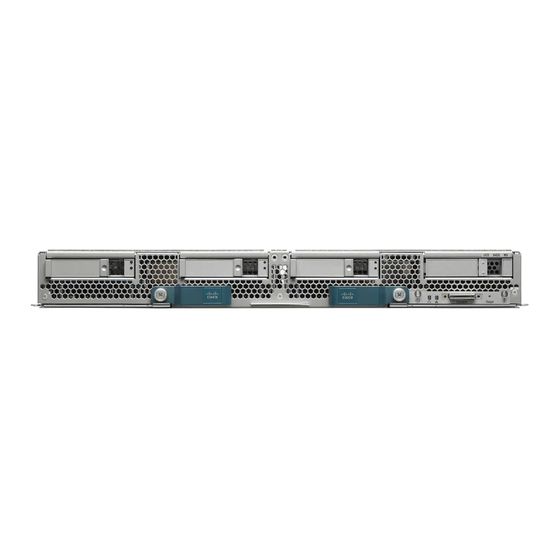
Cisco UCS B420 M3 Installations- und Wartungshinweise - Seite 8
Blättern Sie online oder laden Sie pdf Installations- und Wartungshinweise für Server Cisco UCS B420 M3 herunter. Cisco UCS B420 M3 38 Seiten. High performance blade server
Auch für Cisco UCS B420 M3: Upgrade-Handbuch (8 seiten)

The operating system performs a graceful shutdown and the server goes to standby mode.
Caution
To avoid data loss or damage to your operating system, you should always invoke a graceful shutdown of the
operating system.
Step 3
(Optional) If you are shutting down all blade servers in a chassis, disconnect the power cords from the chassis to completely
power off the servers.
Step 4
Remove the appropriate servers from the chassis.
Removing a Blade Server
You must decommission the server using Cisco UCS Manager before physically removing the blade server.
Procedure
Step 1
Turn off the blade server using either Cisco UCS Manager.
Step 2
Completely loosen the captive screws on the front of the blade.
Step 3
Remove the blade from the chassis by pulling the ejector levers on the blade until it unseats the blade server.
Step 4
Slide the blade part of the way out of the chassis, and place your other hand under the blade to support its weight.
Step 5
Once removed, place the blade on an antistatic mat or antistatic foam if you are not immediately reinstalling it.
Step 6
If the blade server slot is to remain empty, reinstall the slot divider and install two blade server blanking panels to maintain
proper thermal temperatures and to keep dust out of the chassis.
Installing a Blade Server
For installations of UCS blades with differing widths and heights in a chassis, the guideline is to load the heaviest and largest blades
at the bottom of the chassis. Therefore, if a UCS B460 M4 blade server is present, it should be installed at the bottom, followed by
full-width blades such as the UCS B420 M3 (and M4) above the UCS B460 M4, and then half-width blades such as the UCS B200
at the top of the chassis.
Procedure
Step 1
If necessary, remove the slot divider from the chassis.
a) Simultaneously pull up on the left side catch and push down on the right side catch as shown in callout 1 of the following
figure.
8
