1
Package Contents
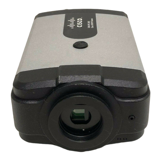
The Cisco Video Surveillance IP Camera package includes these items:
• This Quick Start Guide
(qty. 1)
•
Regulatory Compliance and Safety Information document (qty. 1)
• Camera
(qty. 1)
• 0.9 mm Allen wrench (qty. 1)
• Terminal block for power connection (qty. 1)
• C-mount lens adaptor (qty. 1)
• Snap-on ferrite core (qty. 2)
2
Installing the IP Camera
To install the IP camera, follow these steps:
Procedure
Step 1
Attach the lens to the lens opening on the IP camera:
• If you are using a CS mount lens, screw the lens into the lens opening.
You can use a CS-mount lens with a lens protrusion of up to 5 mm.
• If you are using a C mount lens, screw the C mount lens adapter that is
supplied with the IP camera into the lens opening, then screw the lens
into the adapter.
Step 2
If you are using a DC auto iris lens (recommended for best performance),
connect its cable to the DC auto iris connector on the IP camera.
Step 3
Connect a category 5 or higher network cable to the LAN port on the back
of the camera and to a 10/100BaseT hub, router, or switch. If your network
provides Power over Ethernet (PoE), the IP camera powers on; skip to Step 5.
Connect a 12 V power adapter:
Step 4
a. Put the bare wires at the end of the power adapter wire into the slots at
the rear of the terminal block that is provided with the IP camera.
With the screws on the terminal block facing down, put the wire with
the white stripe into the slot on the right. Put the wire with no stripe into
the slot on the left.
b. Use a small flat-head screwdriver to tighten the screws on the bottom of
the terminal block so that the power adapter wire is attached securely.
c. Plug the terminal block into the power input port on back of the IP
camera.
The tabs on the terminal block must face the bottom of the IP camera.
d. Plug the power adapter into an electrical outlet.
Check the LEDs on the IP camera:
Step 5
• The Ready LED blinks while the IP camera starts up. After 15 to 20
seconds, startup completes and the Ready LED should remain on.
• The Network LED should be on.
Mount the IP camera in the desired location by connecting a mounting device to
Step 6
the threaded mounting hole on the bottom or top of the IP camera.
3
Accessing the IP Camera for the First Time
After you install the IP camera, you can access it by using a PC and configure basic
settings. To do so, follow these steps from a PC that is on the same network as the IP
camera and that is running Microsoft Windows XP Pro with SP 2 or higher:
Procedure
Step 1
Start Internet Explorer 6 or later, enter HTTPS://ip_address in the Address
field, then press Enter.
Replace ip_address with the IP address that the IP camera obtains through
DHCP in your network. If the camera does not obtain this IP address after
90 seconds, enter 192.168.0.100.
The Account window appears.
In the Set Password and Verify Password fields in the Admin column, enter
Step 2
a password for the IP camera administrator.
Enter the same password in both fields. The password is case sensitive and
can contain up to 8 letters, numbers, and special characters, but no spaces.
In the Set Password and Verify Password fields in the Root column, enter a
Step 3
password for accessing the IP camera through a SSH connection.
Enter the same password in both fields. You use this password if you need to
troubleshoot the IP camera through an SSH connection with the assistance
of the Cisco Technical Assistance Center. The password is case sensitive and
can contain up to 8 letters, numbers, and special characters, but no spaces.
In the HTTP area, click the HTTP radio button if you want to allow both
Step 4
HTTP and HTTPS connections to the IP camera.
The default setting is HTTPS, which allows only HTTPS (secure) connections
to the IP camera.
Step 5
Click Apply and wait for the IP camera to reboot.
Step 6
After the IP camera reboots, start Internet Explorer, enter
protocol://ip_address in the Address field, then press Enter.
Replace protocol with HTTPS or HTTP. (You can use HTTP only if you
enabled it Step 4.) Replace ip_address with the IP address that you used in
Step 1.

