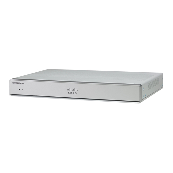
Cisco C1100TG-1N32A Hardware-Installationshandbuch - Seite 35
Blättern Sie online oder laden Sie pdf Hardware-Installationshandbuch für Gateway Cisco C1100TG-1N32A herunter. Cisco C1100TG-1N32A 44 Seiten. Terminal gateway

Install and Connect the Router
2
3
4
5
Identify the connector positive and return DC power
connections. The connections left to right are:
1—Negative DC power connection
2—Negative DC power connection
3—Positive DC Power connection
4—Positive DC Power connection
Measure two strands of copper wire long enough to connect to
the DC power source.
Using a wire-stripping tool, strip each of the two wires coming
from each DC-input power source to 0.25 inch (6.3 mm) ± 0.02
inch (0.5 mm). Do not strip more than 0.27 inch (6.8 mm) of
insulation from the wire. Stripping more than the recommended
amount of wire can leave exposed wire from the power
connector after installation.
Note
Repeat steps 3 and 4 if you desire parallel
connections.
On the power connector, insert the exposed part of the negative
wire into terminal 1 and the exposed part of the positive wire
into terminal 3. Make sure that you cannot see any wire lead.
Only wire with insulation should extend from the connector.
Use the same method for wiring a parallel connection
Note
for terminals 2 and 4.
Hardware Installation Guide for the Cisco 1100 Terminal Gateway
Connecting to DC Power
31
