Crowcon 40/40R Handbuch für Betrieb und Wartung - Seite 11
Blättern Sie online oder laden Sie pdf Handbuch für Betrieb und Wartung für Gas-Detektoren Crowcon 40/40R herunter. Crowcon 40/40R 20 Seiten. Infra-red sf6 and refrigerant gas detector
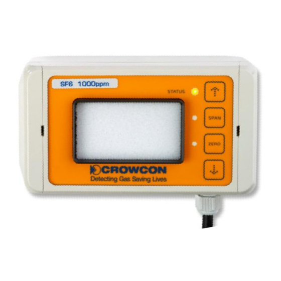
4. Operating the transmitter using the key-pad
The control panel (figure 10) of the transmitter is integrated in the front cover. This is
required if zero or span calibration has to be carried out.
The following operating and display functions are available:
Display elements:
STATUS-LED 3-colours (red, yellow, green)
SPAN-LED
ZERO-LED
Operating elements:
UP
SPAN
ZERO
DOWN
The transmitter can be calibrated and several settings can be made using the display key-
pad.
3-colour STATUS-LED indicates the current operating status. Only one of the three colours
is active at any given time. In addition to this, the conditions "off", "on" and "flashing" exist.
The SPAN and ZERO LEDs have a special purpose. At any given time, only one of these
two LEDs can be active. The three conditions "off", "on" and "flashing" exist here as well.
4.1.
Start-up phase
After the power supply and the selected interfaces have been connected, the transmitter will
begin the start-up phase (STATUS-LED will flash green). This will take less than 2 minutes
and this time is used to check all internal components.
During the start-up phase, the analogue value issued shows the minimum value; the
concentration shows "0".
Depending on the operating mode selected, the following conditions can occur during the
start-up phase:
In 0-20mA mode
In 4-20mA mode
Once the start-up phase is completed and all the test routines have been carried out with
positive results, the transmitter will change to its regular mode, making the measured gas
concentration available via the interfaces. In case a fault was detected during the start-up
phase, the transmitter will change to the operating mode "faulty" (see 4.3).
LED yellow
LED yellow
button
button
button
button
Output current 0mA. After approx. 2 minutes
the pending gas concentration. During the warm-up period, the sensor
signal may still deviate slightly from the exact concentration.
Output current approx. 2mA, then a jump to approx. 4mA. After about
sensor signal may show values of less than 4mA as it can still deviate
slightly from the exact concentration during the warm-up period.
F-Gas Detector Instructions
STATUS
SPAN
ZERO
Figure 10: Display key-pad
depending on