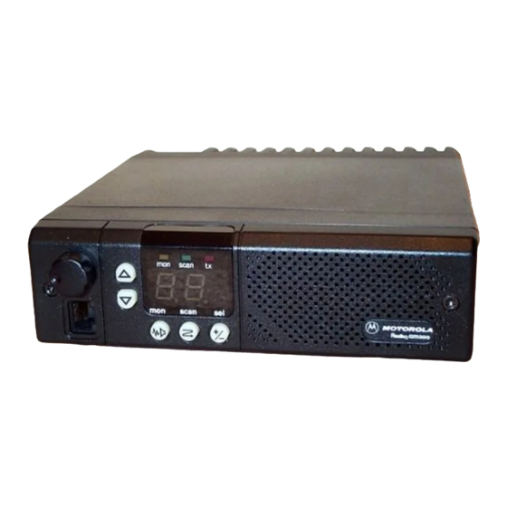
Motorola RADIUS GM300 Service-Handbuch - Seite 39
Blättern Sie online oder laden Sie pdf Service-Handbuch für Zwei-Wege-Radio Motorola RADIUS GM300 herunter. Motorola RADIUS GM300 49 Seiten. 16-channel, conventional fm radio
Auch für Motorola RADIUS GM300: Service-Handbuch (28 seiten), Betriebsanleitung (18 seiten), Betriebsanleitung (19 seiten), Benutzerhandbuch (37 seiten), Betriebsanleitung (2 seiten)

Theory of Operation
Front Panel Boards
Vol/Mic Board
The VOL/MIC circuit board provides mounting and
electrical connection to the microphone jack J11 and the
on-off/volume control R9002. Connections are made to
the logic board via P8. This cable/connector assembly
also contains the two wires which route receiver audio
to the internal 22 ohm speaker mounted in the front
panel.
A 10 ohm resistor, R9001, is located between the CCW
side of the volume control element and ground. At
minimum volume setting, this maintains the attenua-
tion at no greater than 46 dB, to avoid missing a mes-
sage if the volume control is inadvertently turned to
minimum.
2-14
Front Panel Filter Board
The front panel Þlter board is mounted to the front of
the radio chassis. The pins of logic board connectors J8
and J9 pass through this board and are soldered to it.
This board allows capacitive bypassing of all signal
leads leaving the front of the radio chassis. This, com-
bined with the shielding covers over the RF board,
logic board and RF power ampliÞer, reduces the levels
of cabinet radiation to extremely low levels.
In addition, the front panel Þlter board also provides
protection against electrostatic discharge into front
panel controls or indicators. Zener diodes are installed
on any lines which are susceptible to damage from
excessive static voltage transients, limiting voltage
excursions to +27V or -0.7V DC.
68 No.
Name of Manual
March, 1997
