Motorola GP340 ATEX Informationen zum Dienst - Seite 3

Blättern Sie online oder laden Sie pdf Informationen zum Dienst für Radio Motorola GP340 ATEX herunter. Motorola GP340 ATEX 30 Seiten. Professional radio, power distribution and controller
Auch für Motorola GP340 ATEX: Spezifikationsblatt (5 seiten), Benutzerhandbuch (31 seiten), Spezifikationsblatt (2 seiten), Benutzerhandbuch (30 seiten), Benutzerhandbuch (30 seiten), Grundlegendes Benutzerhandbuch (10 seiten), Informationen zum Dienst (32 seiten), Informationen zum Dienst (30 seiten), Informationen zum Dienst (26 seiten), Informationen zum Dienst (24 seiten), Informationen zum Dienst (31 seiten), Informationen zum Dienst (43 seiten)
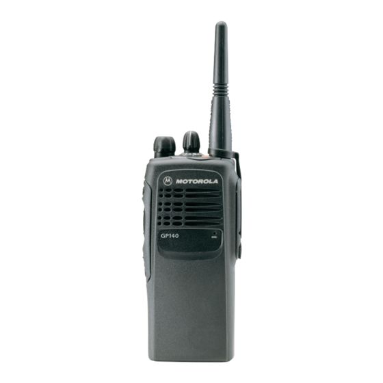
Motorola GP340 ATEX Informationen zum Dienst

Table of Contents

Chapter 1
THEORY OF OPERATION
1.0 Overview ..............................................................................................................1-1
2.0 Radio Power Distribution .....................................................................................1-1
3.0 Controller Circuits ................................................................................................1-2
3.1 Controller Architecture....................................................................................1-2
3.2 MCU Digital Architecture ................................................................................1-2
3.3 Real Time Clock .............................................................................................1-3
3.4 ModB/Vstby Supply ........................................................................................1-4
3.5 Audio/Signaling Architecture ..........................................................................1-4
Chapter 2
TROUBLESHOOTING CHARTS
1.0 UHF/ UHF2 Controller..........................................................................................2-1
1.1 All models except those with PCB 8486458Z03.............................................2-1
1.2 Models with PCB 8486458Z03 .......................................................................2-2
Chapter 3
CONTROLLER SCHEMATICS
1.0 Allocation of Schematics and Circuit Boards .......................................................3-1
2.0 Controller - Set 1 (PCB 8480450Z03, 8485641Z02, 8480587Z01,
3.0 Controller - Set 2 (PCB 8480450Z13/14, 8485641Z06).......................................3-9
4.0 Controller - Set 3 (PCB 8486458Z03, 8486686Z02)..........................................3-15
8485677Z01, 8480641Z03) ......................................................3-3
iii