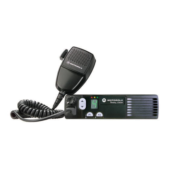
Motorola Radius PM400 Installationshandbuch - Seite 23
Blättern Sie online oder laden Sie pdf Installationshandbuch für Radio Motorola Radius PM400 herunter. Motorola Radius PM400 36 Seiten. Commercial series
Auch für Motorola Radius PM400: Broschüre & Specs (15 seiten)

Accessory Connections
6.2
Connection Plan for Accessories
CAUTION: Do Not short pin 1, 13, or 16 on the accessory connector to Ground; this may damage the
!
radio.
1. Plug the lead with the crimped-on terminal into the #4 socket of the accessory plug. (See Figure
6-1a).
2. Screw the circular terminal into the vehicle chassis.
3. Make all remaining wiring connections per wiring diagram. (See Figure 6-1b).
#15
#16
To Vehicle
Chassis
a. accessory plug
Antenna
Connector
#1
#2
#4
(Blk)
MAEPF-22954-O
Figure 6-1. HLN9328 External Alarm Configuration
Figure 6-2. Accessory Connector
External Alarm
J3-4
On-Off Switch
Red/Wht
Blk
External Alarm Relay Kit
Alarm Device
(Horn or Lights)
b. wiring diagram.
Relay
(Bottom View)
Horn Relay Contacts
or Light Switch
Existing Vehicle Wiring
Accessory
Connector
Connector
Housing
Power
Connector
15
To Vehicle
Battery
MAEPF-23082-A
