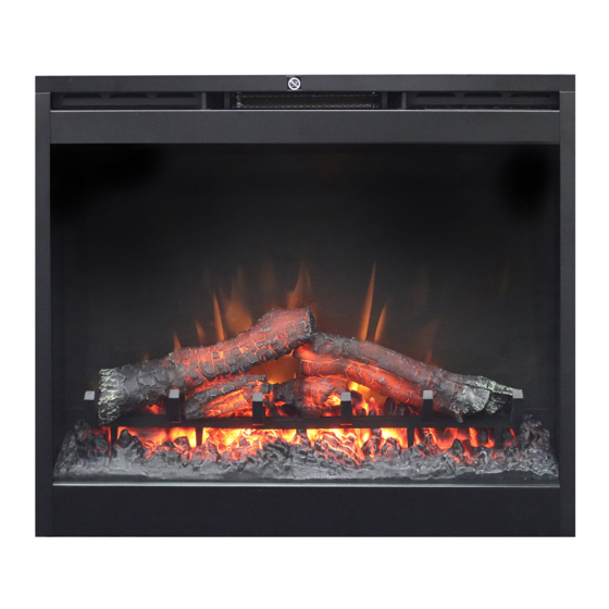
Dimplex 6907560100 Service-Handbuch - Seite 7
Blättern Sie online oder laden Sie pdf Service-Handbuch für Innenkamin Dimplex 6907560100 herunter. Dimplex 6907560100 18 Seiten.

- 1. Exploded Parts Diagram: Df2426, Df2550, Dfg2562, 6905050100-500
- 2. Wiring Diagram: Df2426, Df2550, Dfg2562, 6905050100-500
- 3. Exploded Parts Diagram - Bf9000, 6907560100
- 4. Wiring Diagram - Bf9000, 6907560100
- 5. Light Assembly Replacement
- 6. Flicker Motor/Flicker Rod Replacement
- 7. Heater Assembly Replacement
- 8. Troubleshooting Guide
EXPLODED PARTS DIAGRAM - BF9000, 6907560100
MOD 0-A
1
15
1. Remote Control . . . . . . . . . . . . . . . . . . 3000370500RP
2. Flicker Motor . . . . . . . . . . . . . . . . . . . . 2000210200RP
3. Heater Assembly (with cutout) . . . . . . . 2200491100RP
4. Thermostat . . . . . . . . . . . . . . . . . . . . . 2300150100RP
5. Cutout . . . . . . . . . . . . . . . . . . . . . . . . . 2300270100RP
6. Light Assembly
Mod 0-A: 2 Socket Light Harness . . . . 2500400500RP
Mod B: LED Light Assembly . . . . . . . . 9600810100RP
7. Heater Switch . . . . . . . . . . . . . . . . . . . 2800070700RP
8. 3-Position Switch . . . . . . . . . . . . . . . . . 2800071100RP
9. Remote Control Receiver . . . . . . . . . . 3000380200RP
10. Terminal Block . . . . . . . . . . . . . . . . . . . 4000150100RP
3
5
14
13
6
12
17
7
8
16
10
2
11. Power Cord . . . . . . . . . . . . . . . . . . . . . 4100040300RP
12. Flicker Rod . . . . . . . . . . . . . . . . . . . . . 5901110100RP
13. Partially Reflective Glass . . . . . . . . . . 5901410100RP
14. Control Knob . . . . . . . . . . . . . . . . . . . . 8801080100RP
15. 30" Trim Assembly with Front Glass . . 6907580100RP
16. LED Logset Assembly Mod 0-A . . . . . . 0440590100RP
17. LED Driver Mod 0-A . . . . . . . . . . . . . . 3000390100RP
18. LED Wire Harness . . . . . . . . . . . . . . . . 2500380300RP
19. LED Log Driver Board (Mod B only) . . 3001220100RP
9
4
MOD B
6
19
Mod B . . . . . . . 0440590300RP
Mod B. . . . . . . . . . . . . 3001170100RP
11
17
7
