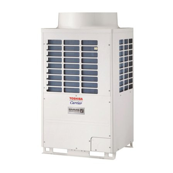
Toshiba Carrier MMY-MAP1446FT9P-UL Installationshandbuch - Seite 20
Blättern Sie online oder laden Sie pdf Installationshandbuch für Klimagerät Toshiba Carrier MMY-MAP1446FT9P-UL herunter. Toshiba Carrier MMY-MAP1446FT9P-UL 33 Seiten.

Screw size and tightening torque
Power supply terminal
Ground screw
◆ Precautions when knocking out knockout holes
• After knocking out the hole to the other side, remove the burr, then we recommend you to paint around the edge
with the repair paint to prevent the rusting.
◆ Control wire connection
1. If conduit is required for the control wiring, connect it to the field wiring panel.
2. If conduit is not required, route the control wiring directly through the field wiring panel.
3. Connect all control wiring to the system interconnecting terminal block and connect the shield to the ground
screw.
U1
U2
S
U3 U4
TO
TO
INDOOR
SHIELD
CENTRAL
UNIT
CONTROLLER
Screw size and tightening torque
control wire terminal
37-EN
Tightening torque
Screw size
ft•lbs (N•m)
M8
4.1 to 4.8 (5.5 to 6.6)
M8
4.1 to 4.8 (5.5 to 6.6)
U5 U6
S
TO
OUTDOOR
SHIELD
UNIT
U
, U
: Control wiring between outdoor units
5
6
U
, U
: Central control device
3
4
S: Shield wire earth
U
, U
: Control wiring between Indoor/Outdoor units
1
2
Tightening torque
Screw size
ft•lbs (N•m)
M4
0.6 to 0.7 (0.80 to 0.96)
– 19 –
9
Address setting
CAUTION
• Complete all electric wiring before setting the addresses.
• To set the addresses correctly, the indoor units must be energize before the outdoor units are energized. Failure
to follow this procedure will result in an "E19" check code being displayed on the outdoor unit control board.
• It normally takes 5 minutes to automatically address one refrigerant line, however this process could take as
long as 10 minutes.
• Simply energizing the system components does not initiate the address process.
• It is not required to run the unit during the address process.
• The address process can be done automatically or manually.
WARNING
• Electrical shock hazard - the electrical control
box contains high voltage parts. All
adjustments for address setting should be
made through the access cover.
Do not remove the electrical control box
cover.
• After completing the address setting the
access cover should be closed and secured
using the screw provided.
■ Automatic address setting
Without central control
or with central control of 1 refrigerant lines (Example 1) :
With central control of 2 refrigerant lines (Example 2) :
When a single refrigerant line is centrally
Address setting
See procedure 1
procedure
Outdoor
Central
control
Control wiring
Indoor
Indoor
diagram
Remote
Remote
control
control
Access
Electrical control
cover
box cover
use Address setting procedure 1
use Address setting procedure 2
Example 1
Example 2
When 2 or more refrigerant lines are centrally
controlled
controlled
See procedure 2
Outdoor
Central
Outdoor
control
Indoor
Indoor
Indoor
Indoor
Remote
Remote
Remote
control
control
control
Access
cover screw
Outdoor
Central
control
Indoor
Indoor
Remote
control
38-EN
