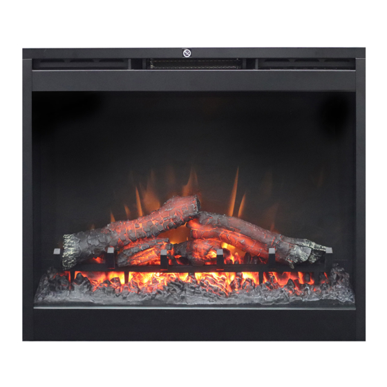
Dimplex BF9000 Benutzerhandbuch - Seite 9
Blättern Sie online oder laden Sie pdf Benutzerhandbuch für Innenkamin Dimplex BF9000 herunter. Dimplex BF9000 19 Seiten. Dimplex
Auch für Dimplex BF9000: Service-Handbuch (17 seiten), Benutzerhandbuch (19 seiten), Benutzerhandbuch (20 seiten), Handbuch zur Fehlersuche (2 seiten), Service-Handbuch (18 seiten)

Fireplace Installation
Figure 3
Figure 4
Wiring
L1
L
N
N
CUTOUT
from the end.
3. Loosen the screw securing
the junction box cover and
remove the cover.
4. Take the cables out from the
junction box, loosen the two
wire twist nuts and remove
the cord set (Figure 3).
5. Route the power supply wire
through the knockout on sup-
plied alternative junction box
cover and secure with a wire
clamp (not supplied)
(Figure 4).
6. Connect the black wire (live)
from the unit to the black wire
from power supply (Figure 4).
7. Connect the white wire
(neutral) from the unit to the
white wire from power supply
LED CONTROL
BOARD
LED LOG
BLOWER
ASSEMBLY
MOTOR
M
ELEMENT
THERMOSTAT
LIGHT HARNESS
ASSEMBLY
M
FLICKER
MOTOR
9
