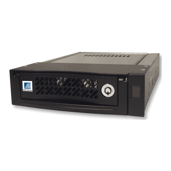
CRU Dataport DE110 Handbuch installieren
Blättern Sie online oder laden Sie pdf Handbuch installieren für Computer-Zubehör CRU Dataport DE110 herunter. CRU Dataport DE110 2 Seiten. Usb 2.0-to-sata/ide

DE110 USB 2.0-to-SATA/IDE Install Guide
Removable USB 2.0-to-SATA/IDE Drive Enclosure
Note: The SATA-to-USB 2.0 DE110 "universal" receiving frame (indicated by the BLUE LED) will accept
both IDE (supports USB 1.1 and USB 2.0) and SATA (supports only USB 2.0) DE110 carriers.
For USB 2.0 operation, a USB 2.0 controller and USB cable (provided) are required.
Windows® 2000/XP/Vista all support USB 2.0.
For easy data backup and restoration, please refer to the Dantz® User's Guide provided
on the Dantz® Retrospect Backup software CD.
DC Power
Connector
Factory Reserved Pins
(no jumper installed)
Figure 1: Receiving Frame Motherboard (rear view)
ID0 & ID1
Jumper is factory-installed on ID0. Change jumper position to Pins 3 & 4 for ID1
designation. ID0 & ID1 are for ID display purposes only. Refer to section "Unit
ID Select Switch Settings" for further information.
Remote Activity LED (RLED)
For IDE drives pins 13 & 14 on the option pin connector provide power for a
remote LED device activity indicator.
Drive Installation
Notes: A #2 Phillips screwdriver will be required during this procedure.
For Parallel ATA drives Master/Slave drive selection, drive can be configured as
Cable Select (recommended) or as Master.
1. Carefully insert the drive into the carrier. Slide the drive towards the Drive
Carrier Board, so that the I/O connector on the drive mates with the connector
on the Drive Carrier Board (figure 2). Turn the drive/carrier assembly over.
2. Fasten the drive into place with four (4) #6-32 Phillips Flat Hd. Screws (fig-
ure 2). Some drives may require minor adjustments before securing into carrier
with screws. If drive supports the Activity Indicator feature, connect one end
of the Activity Indicator Cable (provided) to the drive and the other end to JP1
located on the Drive Carrier Board (figure 2).
3. Install the provided drive cover.
Installing the Receiving Frame
Notes: Use a #2 Phillips screwdriver for this procedure. Refer to your
system motherboard manufacturer's documentation for further information.
Option Pin
Connector
1
3
13
USB 2.0
Connector
Rugged, Reliable, Mobile, Secure
SATA Drive
(not included)
2
4
14
Drive
Carrier
The drive should be installed into the carrier before installing the receiving frame
into the mounting bay of a computer or expansion chassis.
1. Turn OFF power to the computer.
2. Open the computer system according to the manufacturer's instructions. If
necessary, temporarily remove any expansion boards that may make installa-
tion difficult.
3. Locate the USB connector(s) on the system motherboard. Depending o your
system motherboard, it may have one or more 9-Pin USB connectors (with
one typically connected to front USB ports on the PC), or it may have only a
4-Pin USB connector.
If your system motherboard has several 9-Pin USB connectors, proceed to Step 4.
If your system motherboard has only one 9-Pin USB connector, proceed to Step 5.
If your system motherboard has only a spare 4-Pin USB connector (instead of
9-Pin), proceed to Step 6.
1-800-260-9800
Figure 2: Drive Installation Assembly
www.CRU-DataPort.com
TM
Optional Activity
Indicator Cable
(included)
JP1
Drive
Carrier
Board
#6-32
Phillips
Flat
Hd. Screw
(4 each)
