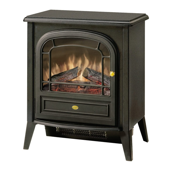
Dimplex DS2307 Service-Handbuch - Seite 9
Blättern Sie online oder laden Sie pdf Service-Handbuch für Herd Dimplex DS2307 herunter. Dimplex DS2307 11 Seiten. Compact stove
Auch für Dimplex DS2307: Benutzerhandbuch (12 seiten), Handbuch zur Fehlersuche (4 seiten)

- 1. Model Number
- 2. Table of Contents
- 3. Operation
- 4. Maintenance
- 5. Exploded PARTS Diagram
- 6. Wiring Diagram
- 7. Switch REPLACEMENT - UNITS with Thermostat
- 8. Thermostat CONTROL REPLACEMENT
- 9. Switch REPLACEMENT - UNITS Without Thermostat
- 10. Flicker Motor/Flicker ROD REPLACEMENT
- 11. Heater Assembly REPLACEMENT
- 12. Power Cord Replacement
- 13. Troubleshooting Guide
Flicker Motor/Flicker Rod Replacement
WARNINg: If the stove was operating prior to servic-
ing, allow at least 10 minutes for light bulbs and heating
elements to cool off to avoid accidental burning of skin.
WARNINg: Disconnect power before attempting any
maintenance to reduce the risk of electric shock or damage
to persons.
1.
Remove 8 screws from top panel.
2.
Sit unit on left side panel.
3.
Remove the 2 legs from the right hand side by remov-
ing a total of 6 screws – these legs are secured to both
the bottom panel and right side panel.
4.
Remove right side panel. (3 screws located on back
and 1 screw located at the top of right side panel)
5.
Remove 2 screws from flicker motor.
6.
Remove the 3 wires from the terminal block that come
from the flicker motor. (brown/white/black)
7.
Insert hand through top panel and hold on to silver
rotisserie (flicker rod) and use other hand to pull on
flicker motor – should make a suction pop noise when
released.
8.
Replace flicker motor and reassemble in the reverse
order as above.
heater Assembly Replacement
WARNINg: If the stove was operating prior to servic-
ing, allow at least 10 minutes for light bulbs and heating
elements to cool off to avoid accidental burning of skin.
WARNINg: Disconnect power before attempting any
maintenance to reduce the risk of electric shock or damage
to persons.
1.
Remove (8) screws from top panel and set aside.
2.
Lay unit on left hand side.
3.
Remove front and rear legs from right side panel –
these legs are secured to both the bottom panel and
right side panel..
4.
Remove right side panel. (3 screws located on back
and 1 screw located at the top of side panel)
5.
Remove (4) screws from heater panel.
6.
Remove heater from heater pan. (total of 4 screws)
7.
Disconnect wiring connections noting their original
locations.
8.
Disconnect cutout wire connection from terminal block
located in right hand side panel with a small slotted
screwdriver.
9.
Remove (2) Z-brackets from heater assembly noting
their original orientation.
10.
Reassemble in reverse order as above.
Power Cord Replacement
WARNINg: If the stove was operating prior to servic-
ing, allow at least 10 minutes for light bulbs and heating
elements to cool off to avoid accidental burning of skin.
WARNINg: Disconnect power before attempting any
maintenance to reduce the risk of electric shock or damage
to persons.
1.
Remove 8 screws from top panel and set aside.
2.
Lay unit on left hand side.
3.
Remove front and rear legs from right side panel –
these legs are secured to both the bottom panel and
right side panel..
4.
Remove right side panel. (3 screws located on back
and 1 screw located at the top of right side panel)
5.
Remove 2 screws from cable clamp bracket located on
back panel.
6.
Remove power cord terminals from terminal block.
7.
Loosen strain relief nuts and remove power cord.
8.
Reassemble in reverse order as above.
9
