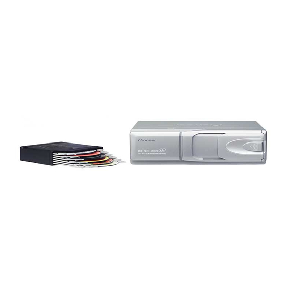
Pioneer CDX-P670 Service-Handbuch - Seite 45
Blättern Sie online oder laden Sie pdf Service-Handbuch für Auto-Empfänger Pioneer CDX-P670 herunter. Pioneer CDX-P670 50 Seiten. Multi-compact disc player
Auch für Pioneer CDX-P670: Benutzerhandbuch (4 seiten), Benutzerhandbuch (4 seiten), Service-Handbuch (50 seiten), Benutzerhandbuch (4 seiten), Benutzerhandbuch (17 seiten)

QQ
3 7 63 1515 0
2. The slide is done in the direction of arrow5 and
remove the Door(B) while spread out the Door(A) in the
direction of arrow4. (Fig.8)
*) The illustration of the text for 12-Disc type but disas-
sembling method is the same for 6-Disc type.
- Removing the Pickup Unit
1. Insert the short pin from the pickup unit in the flexible PCB.
2. Remove the flexible PCB from the connector.
3. Remove the flexible card from the connector.
4. Remove the lead wires to which the spindle motor and carriage motor assy were soldered.
5. Remove the two screws and lift the mechanism PCB up as shown in the figure on the upper right.
At this time, make sure that the motor PCB and flexible relay card are not pulled excessively.
Flexible PCB
TE
L 13942296513
Mechanism PCB
6. Remove screw A and then remove the carriage motor assy, lighting conductor, feed screw holder, feed screw and
belt (see Fig.10).
7. Remove screw B on the main side and the pickup unit together with the guide shaft (see Fig.10).
www
.
http://www.xiaoyu163.com
Flexible card
Short Pin
CRG motor
Feed screw
Guide shaft (main)
x
ao
u163
y
Pickup unit
i
Guide shaft (sub)
http://www.xiaoyu163.com
2 9
8
Door(B)
Erect
Q Q
3
6 7
1 3
1 5
Screw A
Motor bracket
Belt
co
Screw B
.
CDX-P670,P676
9 4
2 8
Door(A)
Motor PCB (handle
0 5
8
2 9
9 4
2 8
with care)
Flexible relay card (han-
dle with care)
Lighting conductor
Screw A
m
Feed screw holder
9 9
Fig.8
9 9
Fig.9
Fig.10
45
