Pioneer CT-W208R - Dual Cassette Deck Service-Handbuch - Seite 27
Blättern Sie online oder laden Sie pdf Service-Handbuch für Empfänger Pioneer CT-W208R - Dual Cassette Deck herunter. Pioneer CT-W208R - Dual Cassette Deck 34 Seiten. Stereo double
Auch für Pioneer CT-W208R - Dual Cassette Deck: Betriebsanleitung (20 seiten), Katalog (10 seiten), Spezifikationen (1 seiten), Betriebsanleitung (32 seiten), Service-Handbuch (34 seiten)
6. ADJUSTMENT
÷
Adjustment points and Measurement points are shown in Fig. 6-5.
6.1 MECHANICAL ADJUSTMENT
6.1.1 Door Damping Check and Adjustment
Set the door spring of the DECK I side to position (A) as shown in Fig. 6-1.
Then, erect the front panel assembly vertically.
Open the doors of DECK I and DECK II at the same time. At this point, confirm
that the difference between the door completely opened and the other door is
within 15 mm. If this standard is not satisfied install the door spring of DECK
I at another position and adjust as follows:
÷
When the door of DECK I opens later than that of DECK II :
Change the door spring of DECK II from (A) to (B).
÷
When the door of DECK I opens faster than that of DECK II :
Change the door spring of DECK I from (A) to (B).
6.1.2 Tape Speed Adjustment
Perform this adjustment in the test mode.
÷
Test Mode Setting
(1) Press the STOP keys of DECK I together with the PAUSE key and the REC MUTE key of DECK II .
(2) The speed becomes normal when the PLAY key is pressed, and double when the FF key is pressed.
(3) To cancel the TEST mode, press the STOP key of DECK I together with the STOP key of DECK II or turn off the power.
N
. o
D
E
C
K
M
o
d
e
T
1
I
D
o
u
b
e l
S
p
e
e
d
S
P
L
A
Y
2
2
3
I
N
r o
m
l a
S
p
e
e
d
N
P
L
A
Y
4
2
6.2 ELECTRICAL ADJUSTMENT
Adjustment Conditions
(1) The mechanical adjustments must be completed first.
(2) The head must be cleaned and demagnetized.
(3) Turn the power on allow the deck to warm up for at least
a few minutes before commencing any electrical adjust-
ments.
(4) The reference signal is 0 dBV = 1 Vrms.
(5) Connect a 10 kΩ load resistance to the OUTPUT terminals.
(6) Unless otherwise specified, the switches listed below are
left in the positions indicated.
DOLBY NR
: OFF
TAPE SELECTOR : NORM
Test Tape
STD–331E
: Playback adjustment (See Fig. 6–2)
STD–632
: NORMAL blank tape
STD–622
: CrO2 blank tape
STD–611
: METAL blank tape
∗ As the reference recording level is 250 nwb/m for STD –
331E, the recording level will be higher by 4 dB for STD –
331B (160nwb/m). When adjusting, pay careful attention
to the type of tape used.
e
t s
T
a
p
e
A
d
u j
t s
n i
g
P
i o
t n
C
h
e
k c
6
0
T
D
3 -
0
1
V
R
8
5
1
W
i
3 (
k
H
) z
r o
V
R
8
0
1
2
9
C
T
1 -
1
1
V
R
8
5
2
W
i
Door Pocket
S
p
e
c
f i
c i
t a
o i
n
s
/
R
t a
n i
g
±
0
0
H
z
6
0
0
H
z
±
h t
n i
1
0
H
z
a
g
a
n i
t s
h t
e
m
e
a
s
u
e r
±
8
0
H
z
5
H
z
±
h t
n i
5
H
z
a
g
a
n i
t s
h t
e
m
e
a
s
u
e r
List of Adjustments
7
Playback Section
(1) Head Azimuth Adjustment
(2) Playback Level Adjustment
7
Recording Section
(1) Bias Oscillator Adjustment
(2) Recording Bias Adjustment
(3) Recording Level Adjustment
NOTE : This unit has an automatic tape selection feature.
Dolby noise reduction manufactured under license from Dolby
Laboratories Licensing Corporation.
"DOLBY" and the double-D symbol are trademarks of Dolby
Laboratories Licensing Corporation.
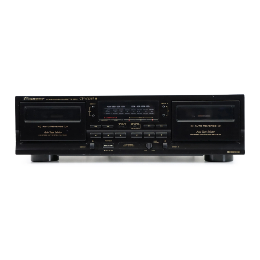
CT-W208R
Front Panel
(A)
Fig. 6–1
s
P (
a l
y
b
a
c
k
F
e r
q
u
e
n
c
) y
m
e
t n
v
a
u l
e
f o
h t
e
s
e t
p
1
(
D
E
C
K
m
e
t n
v
a
u l
e
f o
h t
e
s
e t
p
3
(
D
E
C
K
(B)
R
e
m
a
k r
s
I . )
I . )
27