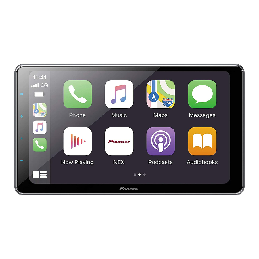
Pioneer DMH-WT76NEX Installationshandbuch - Seite 9
Blättern Sie online oder laden Sie pdf Installationshandbuch für Empfänger Pioneer DMH-WT76NEX herunter. Pioneer DMH-WT76NEX 21 Seiten. Rds av receiver
Auch für Pioneer DMH-WT76NEX: Anweisungen zur Aktualisierung der System-Firmware (9 seiten)

vehicle's location display, and might
otherwise cause reduced display
performance.
• When installing, to ensure proper heat
dispersal when using this unit, make sure
you leave ample space behind the rear
panel and wrap any loose cables so they
are not blocking the vents.
5 cm
Leave ample
space
5 cm
• Do not forcibly insert this unit into the
dashboard/console when installing.
Applying excessive force to the
connectors (HDMI and USB Type-C) may
cause a malfunction.
• The cords must not cover up the area
shown in the figure below. This is
necessary to allow the amplifiers to
radiate freely. (DMH-WC6600NEX/DMH-
WC5700NEX)
Do not cover this area
Installation using the
screw holes on the side
of this product
▶DMH-WT8600NEX/DMH-
WT7600NEX/DMH-WT86NEX/DMH-
WT76NEX
Installation tips
The following procedure describes how to
install this product with an LCD screen
attached to the unit. Depending on the
vehicle or installation location, you may
need to adjust the mounting position of
the LCD screen in order to prevent
impairment of vehicle driving operations.
For details on the mounting LCD screen
dimensions, refer to The adjusting position
and mounting dimension of the display
(page 12) before installing.
WARNING
Do not use a mounting sleeve to install this
unit to prevent it from popping out or
rattling.
1
Adjust the front-back position of the
front panel by removing the flush
surface screws on the front edge of the
unit ( ) then fix the face panel by
using the screw ( ) (optional).
Depending on the vehicle, the front-
back position of the front panel may
need to be adjusted to mount the LCD
screen. Slide the face panel to the front
before installing the unit to the vehicle.
Screw
2
Fasten this product to the factory
radio-mounting bracket.
Position this product so that its screw
holes are aligned with the screw holes
of the bracket, and tighten the screws at
three locations on each side.
TIP
The amount of this unit's protrusion from
the dashboard/console can be adjusted by
shifting the position of the screw hole of
this unit to the factory radio-mounting
bracket.
Factory radio-mounting bracket
If the pawl interferes with
installation, you may bend it down
out of the way.
Dashboard or console
Binding head screw (8 mm) or flush
surface screw
Be sure to use the screws supplied
with this product.
3
Fasten the LCD screen mounting
bracket to the main unit at the suitable
position.
LCD screen mounting bracket
Binding head screw (4 mm × 6 mm)
TIP
The mounting left-center-right position of
the LCD screen mounting bracket can be
changed depending on the vehicle or
installation location of the main unit.
En
9
