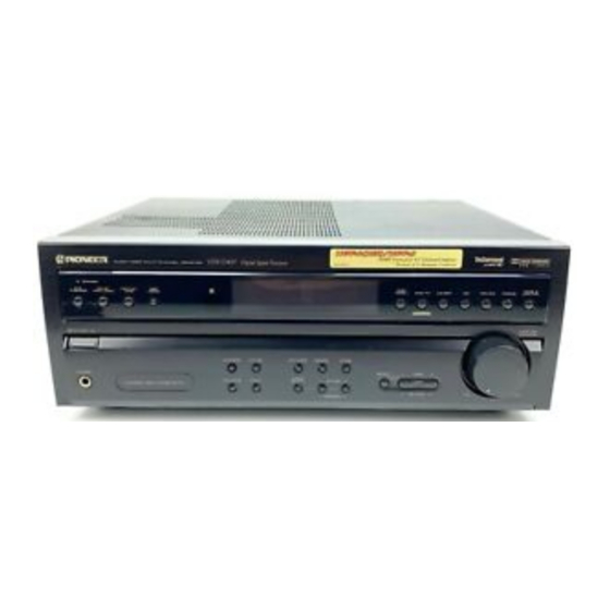
Pioneer VSX-D457 Service-Handbuch - Seite 2
Blättern Sie online oder laden Sie pdf Service-Handbuch für Empfänger Pioneer VSX-D457 herunter. Pioneer VSX-D457 11 Seiten. Audio/video multi-channel receiver
Auch für Pioneer VSX-D457: Service-Handbuch (11 seiten), Service-Handbuch (11 seiten), Service-Handbuch (10 seiten)

VSX-D507S, VSX-D457
1. CONTRAST OF MISCELLANEOUS PARTS
NOTES : ÷ Parts marked by " NSP " are generally unavailable because they are not in our Master Spare Parts List.
÷ The
mark found on some component parts indicates the importance of the safety factor of the part.
Therefore, when replacing, be sure to use parts of identical designation.
÷ Reference Nos. indicate the pages and Nos. in the service manual for the base model.
÷ When ordering resistors, first convert resistance values into code form as shown in the following examples.
Ex. 1
When there are 2 effective digits (any digit apart from 0), such as 560 ohm and 47k ohm (tolerance is shown by
J = 5%, and K = 10%).
= 56 10
560
= 47 10
47k
= R50 ...................................................................... RN2H Â 5 0 K
0.5
= 1R0 ......................................................................... RS1P 1 Â 0 K
1
Ex. 2
When there are 3 effective digits (such as in high precision metal film resistors).
5.62k
7 CONTRAST OF VSX-D507S/ SDXJI, SDXJI/NC and VSX-D457/SDXJI
VSX-D507S/SDXJI, SDXJI/NC, VSX-D457/SDXJI and VSX-D507S/KUXJI are constructed the same except
for the following:
Ref.
Symbol and Description
Mark
No.
ASSEMBLIES
NSP
MOTHER ASSY
P5-1
INPUT ASSY
P6-1
NSP
HP & FAV ASSY
NSP
FRONT & PS ASSY
P5-6
POWER SUPPLY ASSY
P5-7
VIDEO ASSY
P6-2
FL & UCOM ASSY
PACKING
P3-3
Operating lnstructions (English)
Operating lnstructions
(English/Spanish/Chinese)
P3-4
NSP
Warranty Card
P3-5
Remote Control Unit (CU-VSX126)
P3-5
Remote Control Unit (CU-VSX127)
P3-6
Battery Cover
P3-7
NSP
Dry Cell Battery (LR6,AA)
P3-7
NSP
Dry Cell Battery (R6P,AA)
P3-11
Packing Case
P3-13
Sub Instructions (English)
EXTERIOR
P5-11
Power Transformer (T1:AC120V)
P5-11
Power Transformer
(AC110V/120-127V/220V/240V)
P5-12
Fuse (FU2: 6.3A)
Fuse (FU2,FU3: 3.15A)
P5-13
Fuse (FU1: 10A)
P5-14
AC Power Cord
P5-19
Rear Panel
P5-25
Insulator
P5-32
Cord Stopper
P5-40
Spacer
P6-16
Sub Panel
P6-17
Front Panel
Voltage Selector (S1)
Voltage Selector (S2)
NOTE: The numbers in the remarks correspond to the numbers on the exploded diagram, Refer to "EXPLODED VIEWS".
For ASSEMBLES, Refer to " CONTRAST OF PCB ASSEMBLIES" and "2.SCHEMATIC DIAGRAM".
2
= 561 ................................................... RD1/4PU 5 6 1 J
1
= 473 .................................................. RD1/4PU 4 7 3 J
3
= 562 10
= 5621 ........................................... RN1/4PC 5 6 2 1 F
1
VSX-D507S VSX-D507S VSX-D507S
Part No.
/KUXJI
/SDXJI
/SDXJI/NC
AWK7432
AWK7432
AWX7102
AWX7102
AWX7103
AWX7103
AWK7433
AWK7434
AWX7096
AWX7101
AWX7105
AWX7105
AWX7104
AWX7168
ARB7134
Not used
Not used
ARE7166
ARY1051
Not used
Not used
Not used
AXD7158
AXD7158
Not used
Not used
AEX1007
AEX1007
Not used
Not used
AHD7554
AHD7555
ARH7033
ARH7033
ATS7207
Not used
Not used
ATS7209
VEK1026
Not used
Not used
AEK7055
REK1087
REK1132
PDG1015
ADG1157
ANC7624
ANC7625
PNW2766
PNW2766
CM-22C
CM-22B
AEB7118
AEB7124
AAP7041
AAP7041
AMB7486
AMB7486
Not used
AKX-507
Not used
AKX1004
VSX-D457
/SDXJI
AWK7432
AWK7429
AWX7102
AWX7091
AWX7103
AWX7094
AWK7434
AWK7431
AWX7101
AWX7101
AWX7105
AWX7098
AWX7168
AWX7167
Not used
Not used
ARE7166
ARE7164
Not used
Not used
Not used
AXD7156
AXD7158
Not used
Not used
RZN1156
VEM1012
Not used
Not used
VEM-013
AHD7599
AHD7553
ARH7033
Not used
Not used
Not used
ATS7209
ATS7209
Not used
Not used
AEK7055
AEK7055
REK1132
REK1132
ADG1157
ADG1157
ANC7667
ANC7623
PNW2766
AMR7198
CM-22B
CM-22B
AEB7124
AEB7124
AAP7041
AAP7038
AMB7486
AMB7485
AKX-507
AKX-507
AKX1004
AKX1004
Remarks
No.1
No.2
No.3
