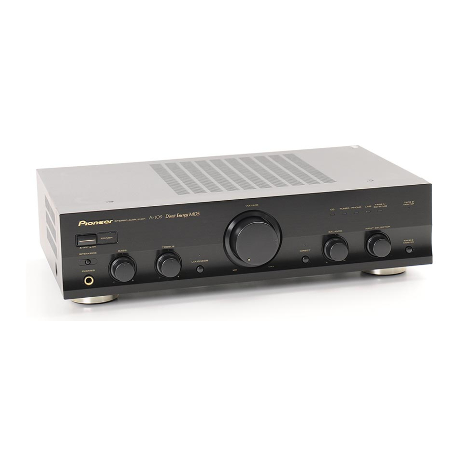
Pioneer A-109 Betriebsanleitung - Seite 8
Blättern Sie online oder laden Sie pdf Betriebsanleitung für Verstärken Pioneer A-109 herunter. Pioneer A-109 32 Seiten. Stereo amplifier
Auch für Pioneer A-109: Betriebsanleitung (12 seiten), Service-Handbuch (6 seiten), Service-Handbuch (6 seiten), Service-Handbuch (6 seiten)

PANEL FACILITIES
[ REAR PANEL ]
1
2 3 4
SIGNAL
PHONO
TUNER
GND
L
R
IN
IN
1
GND (Turntable ground) terminal
2
PHONO terminals
3
TUNER terminals
4
CD terminals
5
LINE terminals
6
TAPE 1/CD-R/MD REC (OUT) terminals
7
TAPE 1/CD-R/MD PLAY (IN) terminals
8
TAPE 2 MONITOR REC (OUT) terminals
9
TAPE 2 MONITOR PLAY (IN) terminals
0
SPEAKERS B terminals (Right channel)
(A-209 only)
-
SPEAKERS B terminals (Left channel)
(A-209 only)
=
VOLTAGE SELECTOR
8
5
6
7 8 9
CD
LINE
TAPE 1/CD-R/MD
TAPE 2 MONITOR
REC
PLAY
REC
PLAY
L
R
IN
IN
OUT
IN
OUT
IN
0
-
SPEAKERS
B
R
L
ª
·
ª
·
A
R
L
@
!
~
AC INLET jack
Connect one end of the power cord to here and the other end
to an AC wall socket, or the AC outlet of an audio timer.
If you are going to be away from home for a long period of
time, disconnect the unit from the wall socket.
AC Power Cord & Socket
This model has two power cords and plug converters. Since
the type of cord and the plug converter which can be used
depends on the power voltage in each region or country, you
must be aware of the power voltage in your country/region. If
cord and/or plug converter are used incorrectly they could
cause a fire or other extremely dangerous situations. Please
make sure you use the correct cord and plug converter. For
more information see page 5.
NOTE:
÷ If you use an other power cord than provided, we cannot
assume the liabilities in what may occur as a result of it.
!
SPEAKERS A terminals (Left channel)
@
SPEAKERS A terminals (Right channel)
=
~
VOLTAGE
SELECTOR
220V
240V
110V
120-127V
AC INLET
The illustration shows the A-209.
