Pioneer A-509R Betriebsanleitung - Seite 5
Blättern Sie online oder laden Sie pdf Betriebsanleitung für Verstärken Pioneer A-509R herunter. Pioneer A-509R 12 Seiten.
Auch für Pioneer A-509R: Service-Handbuch (30 seiten)
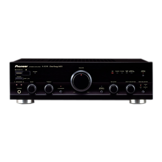
PANEL FACILITIES
(REAR PANEL)
Illustration shows U.K. model
2 3 4 5 6 7 89
1
SIGNAL
GND
PHONO
TUNER
CD
SURROUND
BACK
L
R
IN
IN
IN
1
PHONO terminals
2
SIGNAL GND (Turntable ground) terminal
3
TUNER terminals
4
CD terminals
5
LINE/SURROUND BACK terminals
6
TAPE 1/CD-R/MD REC (OUT) terminals
7
TAPE 1/CD-R/MD PLAY (IN) terminals
8
TAPE 2 MONITOR REC (OUT) terminals
9
TAPE 2 MONITOR PLAY (IN) terminals
0
SPEAKERS
R
LINE/
TAPE1/CD–R/MD
TAPE2 MONITOR
REC
PLAY
REC
PLAY
L
R
R
IN
OUT
IN
OUT
IN
@
-
L
B
CONTROL
OUT
A
L
~
!
0
SPEAKERS B terminals (Right channel)
-
SPEAKERS B terminals (Left channel)
=
AC INLET jack
Connect one end of the power cord to here and the other
end to an AC wall socket, or the AC outlet of an audio timer.
If you are going to be away from home for a long period of
time, disconnect the unit from the wall socket.
~
CONTROL OUT jack (see page 4 )
This jack is for outputting control signals when operating
other components bearing the Î mark with the amplifier's
remote control unit.
!
SPEAKERS A terminals (Left channel)
@
SPEAKERS A terminals (Right channel)
#
AC OUTLET (see page 4 )(European model only)
#
E u r o p e a n
model only
AC INLET
=
AC OUTLET
SWITCHED
100W MAX
5
<ARB7238>