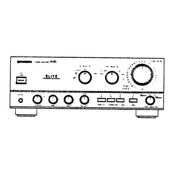
Pioneer A-777 Betriebsanleitung - Seite 5
Blättern Sie online oder laden Sie pdf Betriebsanleitung für Verstärken Pioneer A-777 herunter. Pioneer A-777 16 Seiten. Stereo
Auch für Pioneer A-777: Service-Handbuch (25 seiten), Betriebsanleitung (32 seiten)

CONNECTIONS
(~
Twist the wire core.
Torsader I'ame du cable.
Den Drahtkern zusammendrehen.
Attorcigliate
I'anima del filo.
I
CONNECTING
THE SPEAKER CO,RDS
L
~;
See Fig.
[!]
1.
Strip off the vinyl covering and twist the tip of the wire
core.
2. Loosen the knob and insert the wire core into the
terminal hole.
3. Tighten the knob to fix the wire core in place.
NOTE:
Do not allow the wire core to protrude and touch other terminals or
wires. If the cores of different wires touch, damage may be caused to
your components.
Speaker Impedance
When speaker systems are connected to only one of the SPEAKERS
A or B terminals, such speakers should have rated impedance in the
range of 4-16
n.
When speakers are connected to both the A and B terminals, they
should have a rated impedance in the range of 8-32
n.
I
CONNECTING
INPUT/OUTPUT
CORDS
See Fig.11J
Connect the white plug
@
to the L (left) channel
CD,
and the red plug
@)
to the R (right) channel
0.
Be sure to insert the plugs securely.
TO USE THE COMPONENT
CONNECTED
TO
THE ADPT 2 JACKS (A-777
only)
See Fig.
rn,
[!]
1.
Set the POWER switch to OFF.
2. Remove the two shorting bars from ADPT 2 jacks.
NOTE:
Remove the shorting bars to connect a graphic equalizer to these jacks.
Always keep the bars inserted while the jacks are not in use, and take
care not to lose them.
8
<ARE1194>
EnlFr
CONNEXIONS
CD
Left channel
Canal gauche
@
White plug
Linker Kanal
Fiche blanche
Canale sinistro
WeiBer Stecker
(j)
Rig'"
oh'''''--/6iI ~
~SPinotto
bianco
Canal droit
"-y
..
4i!
Rechter Kanal
~
~
Canale destro
~
@)
Red plug
Fiche rouge
Roter Stecker
Spinotto rosso
I
CONNEXION
DES CORDONS
D'ENCEINTES
Voir Fig.
[!]
1.
Retirer la garniture en vinyle et torsader I' extremite de
I'ame du cable.
2. Desserrer Ie bouton et inserer I'ame dans Ie trou de
borne.
3. Serrer Ie bouton pour fixer I'ame en place.
REMARQUE:
Ne pas laisser sortir rame du cable et toucher d'autres bomes ou cables.
Si les ames de cables differents se touchent, les composants peuvent
etre endommages.
Impedance
des enceintes
Lorsqu'un systeme d'enceintes
est raccorde seulement aux bornes
SPEAKERS A ou SPEAKERS B, les enceintes
doivent
avoir une
impedance nominale de 4
a
16
n.
Lorsque des systemes d'enceintes sont raccordes a la fois aux bornes
SPEAKERS A et B, les enceintes doivent avoir une impedance nominale
I~
de 8
a
32
n.
[ CONNEXION DES CORDONS D'ENTREE/SORTIE
I
Voir Fig. I1J
Connecter la fiche blanche
@
au canal gauche (Ll
CD
et la fiche rouge
@)
au canal droit (R)
0.
S'assurer de bien inserer les fiches a fond.
POUR UTILISER LE COMPOSANT
RACCORDE
AUX PRISES D' ADAPT A TEUR 2 (ADPT 2)
(A-777
seulement)
Voir Fig.
rn,
[!]
1.
Regier l'interrupteur
d'alimentation
(POWER)
sur la
position OFF.
2. Deposer les deux barres de court-circuit
des prises
d'adaptateur
2 (ADPT 2).
REMARQUE:
Deposer les barres de court-circuit
avant de raccorder un egaliseur
a
ces prises. Toujours laisser ces barres inserees pendant que les prises
ne sont pas utilisees et faire attention de ne pas les perdre.
