Pioneer CRT4709 Service-Handbuch - Seite 4
Blättern Sie online oder laden Sie pdf Service-Handbuch für Verstärken Pioneer CRT4709 herunter. Pioneer CRT4709 30 Seiten. Bridgeable four-channel power amplifier
1
6. When you replace a part fixed to the heatsink (Q138, Q141, Q142, Q338, Q341, Q342, D6, D7, Q238, Q241,
A
Q242, Q438, Q441, Q442, Q9, Q10, Q11 and Q12), adjust the position of the part according to the following.
B
C
D
E
Note : Even if the unit shown in the photos and illustrations in this manual may differ from your product, the procedures
described here are common.
F
4
1
2
Put the PCB KIT on blocks.
Put a paper between the block and the PCB KIT,
and outline transistors and diodes.
Put a part to replace in the outline.
Align the bottom of a transistor or a diode with the
top of the PC board, and solder it.
Apply grease, GEM1057 to the back of the part.
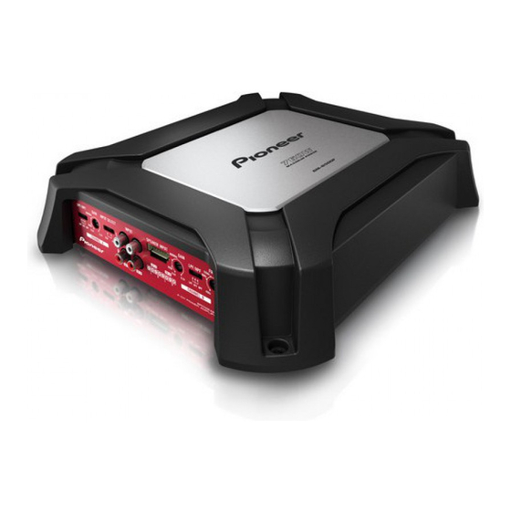
GM-6500F/XZUC
2
3
3
4
4