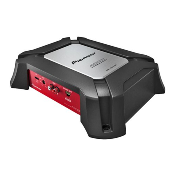
Pioneer GM-3500T/XZES Service-Handbuch - Seite 17
Blättern Sie online oder laden Sie pdf Service-Handbuch für Verstärken Pioneer GM-3500T/XZES herunter. Pioneer GM-3500T/XZES 28 Seiten. Bridgeable two-channel power amplifier

5
Gain : -4.0 dB
LPF
+15.2V
DZ1
MTZ15B
+
R55
14
1.8K
2uF
G060224200020
LPF
SW1A
3
7
IC2B
NJM4565MD
Mute
Q130
D1304
D130
1SS133
20
+
C229
470uF/25
3
1
2
IC2A
NJM4565MD
Q230
R224
D1304
10K
ertor
D230
1SS133
R229
1
R56
2.2K
+
DZ2
470uF/25
MTZ15B
-14.7V
1
Over CurrentProtector
Q7
4
R23
STP60NF06FP
120
133
Q5
1266
Q6
A1266
R22
Q8
120
STP60NF06FP
33
PWM Buffer
Drive
Q11
A1661
R29
22K
R30
1K
Q12
KRC111S
C14
+
1uF/50
Power ON / OFF
Control
5
6
Second Step
First step
Differential Absorption
Differential Absorption
+28V
R35
470/1
R137
1.2K
Q134
Q132
C3875
C3875
C132
C133
82pF/100V
47pF/50V
R140
220
470uF/16
+ C134
R144 1.8K
R143
270
82pF/100V
C136
C135
47pF/50V
Q133
Q135
R138
R129
A1504
A1504
5.6K
1.2K
R237
Q232
Q234
1.2K
C3875
C3875
C232
C233
82pF/100V
47pF/50V
R240
220
C234
+
470uF/16
R244
1.8K
R243
270
C235
47pF/50V
C236
82pF/100V
5K6
Q235
Q233
C36
A1504
A1504
R238
R36
1.2K
-28V
470/1
C12
AC Boost
1000pF
Trance (6:12)
T1
2
L2
C26
0.1uF
D9
+
1N5401
C16
3300uF/25
R32
D10
15K
R31
1N4007
2.2K
6
A-b
Gain : +28.0 dB
Q138 Bias
Drive /
Power Amplification
R141
100
Q141
Q139
C4468
C4373
Q136
A1504
R147
4.7
R142
4.7K
Q138
D600
Q137
R150
C3875
4.7
Q140
Q142
A1695
A1661
R145
100
Q239
R241
100
Q241
C4373
C4468
Q236
A1504
C241
R247
470pF/100V
4.7
R242
4.7K
Q238
C237
D600
0.047uF
Q237
R250
C3875
4.7
Q242
Q240
A1695
A1661
R245
100
DC Protector
C3875
Q42
R45 47K
R48
6.8K
Q41
C3875
R47
4.7K
C41
R46
+
8.2K
R24
47uF/16
10
5
R25
10
C13
1000pF
>
25A
CEK1329
FUSE
1
2
1
FU1
C20
10uF/50V
C64
2
C19
+
1uF
0.1uF
3
GM-3500T/XZUC
7
A
PCB KIT
Over Current
Detection
R162
10K
R160
560
C160
1uF/50
R161
560
Q160
C3875
R165
4.7K
D235
1SS133
R262
10K
R260
560
C260
1uF/50
R264
10K
R261
560
Q260
C3875
R265
4.7K
DC Rectification
D7
C23
+
2200uF/35
C24
+
D6
2200uF/35
POWER
+14.4V
1
VCC
1
Remote
NOTE :
Symbol indicates a resistor.
No differentiation is made between chip resistors and
GND
discrete resistors.
1
Symbol indicates a capacitor.
No differentiation is made between chip capacitors and
discrete capacitors.
NM : No Mount
The > mark found on some component parts indicates
the importance of the safety factor of the part.
Therefore, when replacing, be sure to use parts of
identical designation.
7
8
A
B
SP
4
1
Lout
C
1
3
GND
1
2
Rout
1
1
GND
D
E
F
A
17
8
