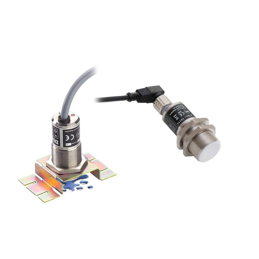
Dinel CPS-24 Gebrauchsanweisung - Seite 6
Blättern Sie online oder laden Sie pdf Gebrauchsanweisung für Schalter Dinel CPS-24 herunter. Dinel CPS-24 14 Seiten. Capacitive proximity switch

Hose clip
Fig. 6: protective PVC hose
5 . Electrical connection
Sensor with NPN or PNP output is allowed to lead only by resistive or inductive lead. Positive sup-
ply voltage (+U) is connected to the brown conductor BN (1), negative (0 V) to the blue conductor
BU (3) and the leads (only NPN or PNP type of output) to the black conductor BK (4). The capacity
loads and low resistance loads (bulb) is evaluated by the sensor as short circuit.
The line from CPS-24N to the connecting device is from a suitable three wire (min. 3x0.5 mm2)
cable, in the case of variant CPS-24Xi using a two wire (min. 2x0.5 mm2) cable. In the event that
a disassemblable socket ELWIKA or ELKA 4012 K PG7 are used, the max. outer diameter of the
cable is 6 mm. Connector socket is not part of the sensor.
Fig. 7: NPN type sensors connection
Fig. 9: PNP type sensors connection
Legend:
(*) – Numbers of terminals inside of the connector
BK – Black
BN – Brown
BU – Blue
Electrical connection can only be made when de-energized!
The source of the power voltage must comprise of a stabilised safe low power source with
galvanic separation. In the event that a switch-mode power supply is used, it is essential
that its construction effectively suppresses common mode interference on the secondary
side. In the event that the switch-mode power supply is equipped with a PE safety terminal,
it must be unconditionally grounded! Spark-safe devices (type CPS-24) must be powered
from a spark-safe power source meeting the above-mentioned requirements.
© Dinel, s.r.o.
CPS–24
Protective hose
Cable
(version "N")
(version "P")
In the case of vertical mounting in outer areas or in the
case of high mechanical exertion we recommend to in-
stall in Variant "B" protective hose on the cable (see
figure).
Fig. 8: NAMUR type sensors connection
Fig. 10: Inside of the connector socket
(version "Xi")
Output (BK)
+U (BN)
0V (BU)
6
