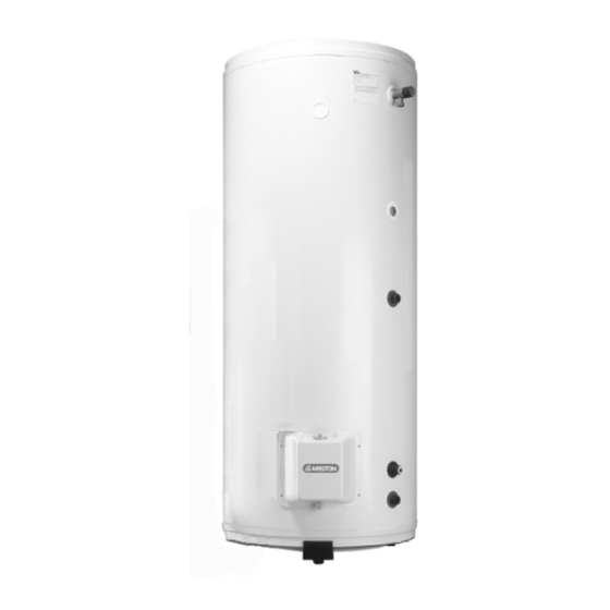
Ariston ST 100 ProTech Handbuch für Installation und Gebrauch - Seite 18
Blättern Sie online oder laden Sie pdf Handbuch für Installation und Gebrauch für Warmwasserbereiter Ariston ST 100 ProTech herunter. Ariston ST 100 ProTech 24 Seiten. Unvented hot water storage cylinders
Auch für Ariston ST 100 ProTech: Benutzerhandbuch (16 seiten), Anweisungen für Installation, Wartung und Gebrauch (36 seiten), Anweisungen für Installation, Wartung und Betrieb (34 seiten)

www.tradeplumbing.co.uk Call Sales On 08708034288
4.
MAINTENANCE
4.1
P
T
RO
ECH
A
-
NTI
CORROSION
4.2
T
C
-
HERMAL
UT
4.3
I
H
MMERSION
EATER
4.4
U
C
NVENTED
ONTROLS
www.tradeplumbing.co.uk Call Sales On 08708034288
18
To ensure efficient safe operation, it is recommended that the appliance is
serviced annually by a competent person.
After servicing, preliminary electrical system checks must be carried out to
ensure electrical safety (i.e. polarity, earth continuity, resistance to earth and
short circuit).
WARNING: SWITCH OFF THE POWER SUPPLY BEFORE WORKING ON
THE APPLIANCE.
S
YSTEM
Trouble-shooting:
1) The green L.E.D. is NOT on:
- Check to see that the circuits electric plug is connected (if not,
- Check to see that the P.C.B, is supplied with electricity (if not, replace
- Check to see that 230 V electricity is supplied (if not, ensure that 230 V
- If all these checks fail to locate the problem, replace the electronic
2) The red L.E.D. is on:
- Check to see that the tank is filled with water (if not, fill it before
- Check to see that the clip-on circuit connector is in the proper position
- Check to see that the electrodes connection lead is property connected
- Check to see that the connection lead to the tank is properly connected
- Check to see that the two leads from the clip-on circuit connector are
- If all these checks fail to locate the problem, replace the electronic
N
OTE
1) Disconnect the two supply cables from the P.C.B. to the supply terminal;
2) Disconnect the clip-on circuit connector and polarising slot which
connects the circuit to the tank and the electrode;
3) Disconnect the P.C.B. from its supporting plate (plastic clips in the 4
corners) and;
4) Replace the defective circuit with a new one, then re-install in reverse
order to the above.
If the thermal cut-out has operated the cause must be found before resetting
(
)
OUT
S
(see section 5).
(
)
Should the immersion heater(s) become scaled, we would recommend that
S
the immersion heaters be replaced, also ensure that the thermostat is set
below 60
Check controls as per the following:
1) Line strainer - with the water supply turned off remove screen from
strainer and clean of any detritus;
2) Expansion vessel - with the water supply turned off and taps open, check
expansion vessel pressure and top up as necessary;
3) Temperature & pressure relief valve - with the water supply turned on,
check manually by lifting the test lever/turning the test knob (ensure valve
closes after testing);
connect);
the supply cable);
is supplied);
circuit (installer).
carrying out the following checks);
(if not, position correctly);
(to check this, gently pull on it) (if not, replace the electrode);
to the tank (if not, connect properly); .
not damaged, stripped, etc. (if so, replace the electrode);
circuit.
: To replace the P.C.B, there is no need to drain the cylinder;
O
C to prevent further scale formation.
