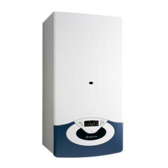
Ariston GENUS 24 FF Installations- und Wartungsanweisungen - Seite 39
Blättern Sie online oder laden Sie pdf Installations- und Wartungsanweisungen für Boiler Ariston GENUS 24 FF herunter. Ariston GENUS 24 FF 44 Seiten. Wall-hung gas boiler
Auch für Ariston GENUS 24 FF: Benutzerhandbuch (21 seiten)

menù impostazione - regolazione - diagnostica
descrizione
note
8 5 1 Abilitazione avviso di
manutenzione
8 5 2 Cancellazione dell'avviso di
manutenzione
Eff ettuata la manutenzione il parametro permette la
cancellazione dell'avviso.
8 5 3 NON ATTIVO
8 5 4 Versione Hardware scheda elettronica
8 5 5 Versione Hardware scheda elettronica
8 5 6 Versione Software schedino per periferiche BUS
8 6 STATISTICHE
8 6 0 Numero ore funzionamento bruciatore in riscaldamento
(XXh)
8 6 1 Numero ore funzionamento bruciatore in sanitario (XXh)
8 6 2 Numero distacchi di fi amma
8 6 3 Numero cicli di accensione
8 6 4 NON ATTIVO
8 6 5 Durata media delle richieste di calore
8 7 NON ATTIVO
8 8 ELENCO ERRORI
8 8 0 Ultimi 10 errori
Il parametro consente di visualizzare gli ultimi 10 errori
segnalati dalla caldaia indicando giorno, mese e anno.
Accedendo al parametro vengono visualizzati in sequenza gli
errori verifi catesi dal numero E00 al numero E99.
Per ogni singolo errore viene visualizzato in sequenza:
E00 - numero errore
108 - codice dell'errore
A15 - giorno in cui si è verifi cato l'errore E00
B09 - mese in cui si è verifi cato l'errore E00
C06 - anno in cui si è verifi cato l'errore E00
8 8 1 Reset lista errori
8 9 DATI CENTRO ASSISTENZA
8 9 0 Inserimento Nominativo e numero di telefono del Centro
Assistenza
Sul display appare "Nome Centro Assistenza", premere il tasto
MENU/OK ed iniziare l'inserimento delle lettere ruotando
l'encoder. Ad ogni singola lettera inserita premere il tasto
MODE per confermare e proseguire nell'inserimento della
lettera seguente. Premere il tasto MENU/OK.
Ruotare l'encoder, sul display appare "Telefono Centro
Assistenza"
Premere il tasto MENU/OK ed iniziare l'inserimento dei
numeri ruotando l'encoder. Ad ogni singolo numero
inserito premere il tasto MODE per confermare e proseguire
nell'inserimento del numero seguente. Al termine premere il
tasto MENU/OK.
MENU I
NFO
Premendo il Tasto I
si accedere alla visualizzazione dei dati indicati
NFO
nella tabella sotto riportata. Continuando a premere il tasto INFO, si
scorrono le varie informazioni. Per uscire premere il tasto Esc.
Ora della giornata
Pressione circuito riscaldamento (bar)
Temperatura esterna (°C)
- solo con sonda esterna collegata (optional)
Temperatura interna (°C)
- solo con sensore ambiente modulante collegato (optional)
Portata acqua sanitaria (l/m)
Temperatura impostata riscaldamento (°C)
Temperatura impostata sanitario (°C)
Mesi mancanti alla prossima manutenzione
Telefono e Nome CAT
(viene visualizzato se impostato al parametro 890)
Temperatura comfort sanitario (°C) - se attivata
Funzione Auto "Abilitata" o "Disabilitata" si illumina il simbolo sul display
Temperatura misurata accumulo - solo per caldaie con accumulo
range
0 = OFF
OFF
1 =ON
Reset? OK= Cancellare
ESC = No
da E00 a E99
Reset? Ok = Si
Esc = NO
settings - adjustment - problem identifi cation menus
description
notes
8 5 1 Enable Maintenance advice
8 5 2 Maintenance Warning Reset
to erase the advice for maintenance
8 5 3 NOT ACTIVE
8 5 4 P.C.B Hardware version
8 5 5 P.C.B Software version
8 5 6 P.C.B BUS Software version
8 6 STATISTICS
8 6 0
Hours Burner On (Central Heating) (XXh)
8 6 1
Hours Burner On (Domestic Hot Water) (XXh)
8 6 2
Number of Flame Faults
8 6 3
Numbeer of ignition Cycles
8 6 4
NOT ACTIVE
8 6 5
Heat request Duration
8 7 NOT ACTIVE
8 8 ERROR HISTORY
8 8 0 Last 10 errors
This parameter makes it possible to see the last 10 errors
shown by the boiler as well as the relevant day, month and
year. Access the parameter to bring up the sequence of errors
from number E00 to number E99.
The following data is shown in a sequence for each single
error:
E00 - error number
1 08 - error code
A 15 - day when the error occurred E00
B 09 - month when the error occurred E00
C 06 - year when the error occurred E00
8 8 1 Reset Error List
8 9 SERVICE
8 9 0 Insert Service Name
To enter the name of Technical Assistance Service press the
M
/O
button.
ENU
K
"Assistance Name" appears on the display unit; press M
and enter each individual letter at a time, confi rming them by
pressing the C
button. When the process is complete, press
LOCK
the M
/O
button to store the information.
ENU
K
"Telephone Assistance" will appear on the display.
Press the M
/O
button and start entering the numbers by
ENU
K
turning the encoder. After each number has been entered
press the Clock button to confi rm and continue with the
insertion of the following number.
When the process is complete, press the M
INFO MENU
Press the INFO button to access to the INFO MENU.
Press the INFO button to scrolls through various information in the table
below. Press the Esc button to restore the normal display screen.
Time of day - Hour
Heating circuit pressure (bar)
External temperature (°C) -
only with external sensor connected
Room temperature (°C) -
only active when the BUS device is connected
D.H.W. Flow rate (l/m)
Set C.H. temperature (°C)
Set D.H.W. temperature (°C)
Month until next maintenance
Technical Assistance Centre telephone number and name
(only display if setted parameters 890 - 891)
D.H.W. comfort temperature (°C) - if activated
AUTO Function - "enabled" or "disabled"
Storage temperature °C - only for boiler with storage
value
0 = OFF - 1 = ON
OFF
Reset? OK= Yes Esc
= No
from E0 to E9
Reset? Ok=Yes
Esc=No
/O
ENU
K
/O
button.
ENU
K
39
