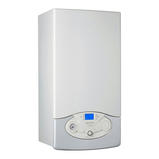
Ariston PREMIUM EVO SYSTEM 24 Installations- und Wartungsanweisungen - Seite 18
Blättern Sie online oder laden Sie pdf Installations- und Wartungsanweisungen für Boiler Ariston PREMIUM EVO SYSTEM 24 herunter. Ariston PREMIUM EVO SYSTEM 24 48 Seiten. Condensing wall-hung gas boiler

installazione
Collegamento condotti aspirazione e scarico fumi
La caldaia è idonea a funzionare in modalità B prelevando aria
dall'ambiente e in modalità C prelevando aria dall'esterno.
Nell'installazione di un sistema di scarico fare attenzione alle tenute
per evitare infi ltrazioni di fumi nel circuito aria.
Le tubazioni installate orizzontalmente devono avere una pendenza
discendente (3%) verso l'apparecchio per evitare ristagni di condensa.
Nel caso di installazione di tipo B il locale in cui la caldaia viene
installata deve essere ventilato da una adeguata presa d'aria
conforme alle norme vigenti.
Nei locali con rischio di vapori corrosivi (esempio lavanderie, saloni
per parrucchiere, ambienti per processi galvanici ecc.) è molto
importante utilizzare l'installazione di tipo C con prelievo di aria per
la combustione dall'esterno. In questo modo si preserva la caldaia
dagli eff etti della corrosione.
Per la realizzazione di sistemi di aspirazione/scarico di tipo coassiale
è obbligatorio l'utilizzo di accessori originali.
I condotti scarico fumi non devono essere a contatto o nelle vicinanze
di materiali infi ammabili e non devono attraversare strutture edili o
pareti di materiale infi ammabile.
Nel caso di installazione per sostituzione di una vecchia caldaia il
sistema di aspirazione e scarico fumi andrà sempre sostituito.
La giunzione dei tubi scarico fumi viene realizzata con innesto
maschio/femmina e guarnizione di tenuta.
Gli innesti devono essere disposti sempre contro il senso di
scorrimento della condensa.
Tipologie di collegamento della caldaia alla canna fumaria
- collegamento coassiale della caldaia alla canna fumaria di
aspirazione/scarico,
- collegamento sdoppiato della caldaia alla canna fumaria di scarico
con aspirazione aria dall'esterno,
- collegamento sdoppiato della caldaia alla canna fumaria di scarico
con aspirazione aria dall'ambiente.
Nel collegamento tra caldaia e canna fumaria debbono essere
impiegati prodotti resistenti alla condensa. Per le lunghezze e cambi
di direzione dei collegamenti consultare la tabella tipologie di scarico.
I kit di collegamento aspirazione/scarico fumi vengono forniti
separatamente dall'apparecchio in base alle diverse soluzioni di
installazione.
Il collegamento dalla caldaia alla canna fumaria è eseguito in tutti gli
apparecchi con tubazioni coassiali ø60/100 o tubazioni sdoppiate ø
80/80.
Per le perdite di carico dei condotti fare riferimento al catalogo
fumisteria. La resistenza supplementare deve essere tenuta in
considerazione nel suddetto dimensionamento.
Per il metodo di calcolo, i valori delle lunghezze equivalenti e gli
esempi installativi far riferimento al catalogo fumi
Utiliizare eslusivamente Kit scarico fumi per caldaie a
condensazione
ATTENZIONE
Assicurarsi che i passaggi di scarico e ventilazione non
siano ostruiti.
Assicurarsi che i condotti di scarico fumi non abbiano
perdite
18
installation
Connecting the Flue
The boiler is designed to operate in B mode (by drawing air from the
room) and in C mode (by drawing air from outside).
When installing an exhaust system be careful when handling the
seals, in order to avoid fl ue gas leaking into the air circuit.
Horizontally-installed piping must have a downward incline of 3% so
as to avoid the build-up of condensate.
Nel caso di installazione di tipo B il locale in cui
When type B installation is used, the room in which the coiler is
installed must be ventilated using a suitable air inlet which complies
with current legislation.
In rooms where corrosive vapours may be present (for example,
laundry rooms, hair studios, rooms where galvanic processes take
place, etc.) it is important that type C installation is used, with air for
combustion drawn from outside. In this way the boiler is protected
from the eff ects of corrosion.
When implementing coaxial suction/exhaust systems the use of
authentic accessories is obligatory.
The fl ue gas exhaust ducting must not be in contact with or placed
near fl ammable materials, and must not cross building structures or
walls made using fl ammable material.
When replacing an old boiler, the ventilation and fl ue gas exhaust
system must always be replaced.
The fl ue gas exhaust ducting joint should be created using a male/
female coupling and a seal. Couplings should always be arranged so
that they go against the direction of the condensate fl ow.
Types of boiler - fl ue exhaust connection
- coaxial connection of the boiler to the suction/exhaust ducting
- split connection of the boiler to the exhaust ducting with air
suction from outside
- split connection of the boiler to the exhaust ducting with air
suction from the room.
Products which are resistant to condensate must be used in the
connection between the boiler and the fl ue gas exhaust. For details
relating to connection lengths and direction changes, please consult
the "exhaust types" table.
The suction/exhaust ducting connection kits are supplied separately
from the appliance, according to diff erent installation solutions.
The boiler is set up for connection to a coaxial suction and fl ue gas
exhaust ducting system.
If there is any loss of pressure in the piping, please refer to the gas
fl ue accessories catalogue. Supplementary resistance must be borne
in mind during the sizing process mentioned above.
For the calculation method, equivalent length values and installation
examplesplease refer to the gas fl ue accessories catalogue.
WARNING
Make sure that the fl ue gas exhaust and ventilation
ducting are not obstructed.
Make sure that there are no leaks along the fl ue gas
exhaust ducting.
