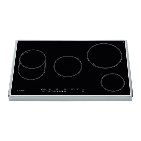
Ariston NRO 642 D Z Betriebsanleitung - Seite 3
Blättern Sie online oder laden Sie pdf Betriebsanleitung für Kochfeld Ariston NRO 642 D Z herunter. Ariston NRO 642 D Z 13 Seiten.

i in
The appliance must be installed
supporting surface.
Any deformities caused by improper fixing could
affect the features and operation of the hob.
The thickness of the supporting surface
taken into account when choosing
screws for the fixing hooks:
0 mm thick: 17. mm screws
40 mm thick: 7. mm screws
Fix the hob as follows:
1. Use short flat-bottomed screws to fix the 4
alignment springs in the holes provided at the
central point of each side of the hob.
2. Place the hob in the cavity, make sure it is in a
central position and push down on the whole
perimeter until the hob is stuck to the supporting
surface.
. For hobs with raised sides: After inserting the hob
into its cavity, insert the 4 fixing hooks (each has its
own pin) into the lower edges of the hob, using the
long pointed screws to fix them in place, until the
glass is stuck to the supporting surface.
lect ical connection
r
r
UNDERSIDE OF HOB
on a perfectly level
should be
the length of the
g
Voltage and
Electrical cable
mains frequency
230-240V 1+N ~
220-240V 1+N ~
50/60 Hz
r
5 6
3
5 6
3
3
5 6
5 6
Voltage and
Electrical cable
mains frequency
400V - 2+N ~
50/60 Hz
230-240V 3 ~
220-240V 3 ~
50/60Hz
400V - 2+2N ~
50/60 Hz
3
5 6
Terminal board picture
3
Wire connection
: yellow/green;
N: the two blue wires
together
L: brown and black
together
Wire connection
: yellow/green;
N: the two blue wires together
L1: black
L2: brown
: yellow/green;
N1: blue
N2: blue
L1: black
L2: brown
5
5
see
