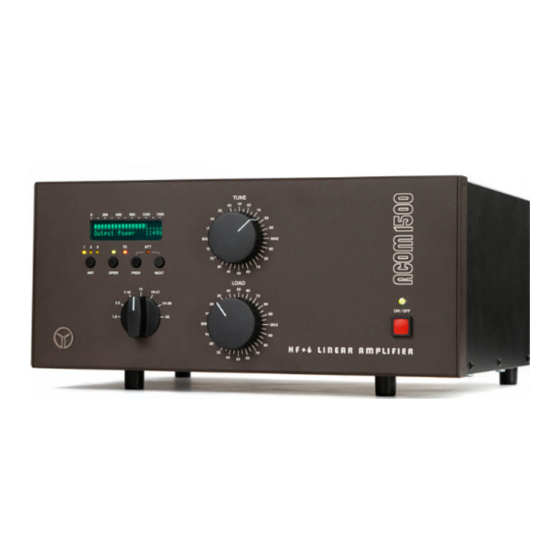
Acom 1500 Ersatz-Handbuch - Seite 2
Blättern Sie online oder laden Sie pdf Ersatz-Handbuch für Verstärken Acom 1500 herunter. Acom 1500 9 Seiten. Tube replacement

c) Before proceeding, please make sure that no residual DANGEROUS VOLTAGES are
present in the amplifier. For this purpose take approximately 1m of WELL-INSULATED
lead (adequate for 3000V). Bare it to about 1cm at both ends.
Tighten one end of the wire under the GROUND STUD (on the rear
panel). Only
AFTERWARDS, holding the wire BY THE INSULATION, at a distance of minimum 10cm (4
Inch), ground with the tip of its second end momentarily and consecutively each
part on the HV rectifier PCB, especially:
- the HV output J3;
- the wire-wound resistor R12 on its both sides;
- the four HV diodes on their both sides.
With the tip of the same
permanently grounded
wire, on the MAINS PCB ground
momentarily the diode D19 on its both sides (D19 is located at the PCB edge, near
the powerful MOSFET transistor which is installed on the chassis).
3.
Removing the Screen above the RF Deck.
Using a Philips-1 screwdriver, unscrew 18 pcs of countersunk-head screws to
release the aluminum cover above the RF deck. Lift and pull the cover to remove
it.
Repeat step 2(c) to discharge any residual high voltages, this time grounding
momentarily the copper strip of the plate anti-parasitic suppressor and the tube
anode cap with the tip of the
permanently grounded
wire.
2
