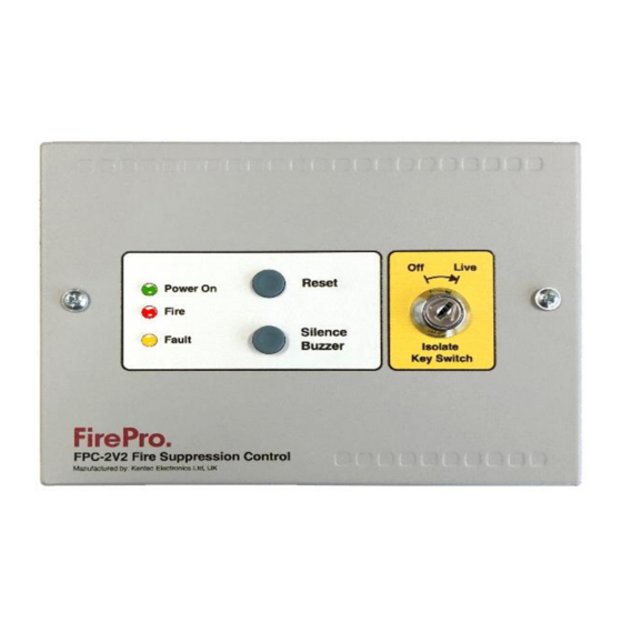
FirePro FPC-2 Handbuch für Betrieb und Wartung - Seite 6
Blättern Sie online oder laden Sie pdf Handbuch für Betrieb und Wartung für Controller FirePro FPC-2 herunter. FirePro FPC-2 7 Seiten. Fire control panel system isolation
Auch für FirePro FPC-2: Betriebs- und Installationshandbuch (14 seiten), Handbuch für Betrieb und Wartung (8 seiten), Schnellstart-Handbuch (2 seiten)

4. Connecting to Master Fire Panel
General
To connect to a Master Indicator Panel, there is some connections to be made between the panels and then some
programming configuration in the Master Panel.
FPC-2 as a sub-panel with stand-alone detection and activation
Following explains connection and configuration to Sigma
XT Master Panel. The concepts will be similar to other
brands/types on master panel.
The connections are 24vDC power which can come from
Sigma XT – or an appropriate external source, and a
Single detection Zone is require on Sigma to allow inputs
from FPC-2.
The EOL Resistor ensures that this circuit is monitored
from the Sigma XT panel.
Once the connections are complete. The Sigma XT panel
must be programmed correctly to set up the FP-C2 as a
remote device. This must be done so that the FP-C3 is
not treated as a regular detection device.
programmed correctly, the FP-C2 will alert the main
Sigma XT panel of any alarm or fault states.
On the Sigma XT FIP, enter Access Level 2 by turning the key in
"Enable Control" port on the Detection card (top card) or by releasing
the read switch by opening the inner Perspex door.
6. Enter Access level 3 on the Detection Card (top card) by
moving the "Write Enable" switch to the right. The "System
Mode" LCD display will read "00".
7. The FIP's detection options are numbered. Using the
controls on the Detection Card, navigate the menu until the
"System Mode" LCD display reads "7#" (# being the number of the detection circuit you wish to connect
to). To do this press the "Mode (+10)" button until the first number is "7" and then press the "Select
(+1)" button until the display shows the correct detection circuit.
8. The detection circuit number will have a flashing dot next to the
number, indicating that it is programmed for conventional detection.
Press the "Enter" button to change the detection circuit to S/C mode.
This will cause the flashing dot to turn off.
9. Exit Access level 3 by moving the "Write Enable" switch to the left and exit Access level 2 by closing the
inner door or by turning the key in the "Enable Control" port.
FPC-2 as a activation Module only
This configuration uses the FPC-2 as an activation module only. This can be established with any style of AS Panel.
Individual configurations will be dependent on the specifics of the master
panel.
Connection will be required for the Power Supply. The activation device needs
to connect to the detection circuit on the FPC-2, this needs to meet the
detection circuit criteria.
activation of the extinguishant system is immediate.
Fire and Fault reporting will require connection back to the master panel.
To make the FPC-2 compatible with an addressable input module, move
jumpers J1 and J2 from their default positions (position A) to position B. The
FIRE NO and C terminals can now be connected directly to the addressable
input module.
Alarm and fault conditions will be indicated on a addressable fire alarm control
panel.
Note: The volt free contact function is not available when the contacts are
being used to signal and addressable input module.
fp_c2_m5.3
When
Once the FPC-2 receives a detection advice –
Page 6 of 7
