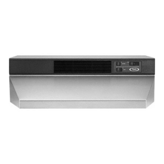
Whirlpool GZ8336 Series and Installationsanweisungen und Gebrauchs- und Pflegeanleitung - Seite 5
Blättern Sie online oder laden Sie pdf Installationsanweisungen und Gebrauchs- und Pflegeanleitung für Lüftungshaube Whirlpool GZ8336 Series and herunter. Whirlpool GZ8336 Series and 10 Seiten. 30" and 36" convertible range hood
Auch für Whirlpool GZ8336 Series and: Installationsanleitung und Gebrauchs- und Pflegeanleitung (20 seiten)

®Fromthe diagramsbelow,
sebct the diagramfor your
instaihtion.
Vented
installations: Cut the vent
system and electrical wiring
access holes as required.
Either
wiring
hole can be used.
Non=vented installations:
Cut only
the one 1=1/4" (3.2 cm) dia. wiring
access hole required,
if wiring
through
the top, use location
shown in VERTICAL vent systems.
If wMng
through
the back, use
location
shown in HORIZONTAL
vent system.
6-1/4"
screws
bottom
cover
Figure 3
5-1/8"
1-3/8"
wall
1-1/4"
(l&0
crn)
(3,5 cm)
(3.2 cm)
2-1/8"
dia, ho_e (5.4 crn)
3-1/4" x 10" (8.3 x 25.4 cm)
RECTANGU LAR VERTICAL
vent system
centedine
..
(1&1 era)
3ol/4" x 10" (8.3 x 25.4 era)
HORIZONTAL vent system
Prepare and install
the hood
|
Excessive
Weight Hazard
[
|
Use two or more people to move[
and install range hood.
[
Failure to do so can result in
back or other
njary.
For Steps 5 through
10, refer to
Figure 3.
® Set hood upside down on a
protective
covering
such as
cardboard
or large towel.
® Remove bottom cover
screw's and bottom
cover.
7m Remove filters.
® Remove wiring
box cover
and screws.
® To make the hood lighter
and easier to install, it is
recommended
that the blower
assembly
be removed.
To remove:
a) Disconnect
blower wiring
plug.
b) Loosen, but do not remove,
knurbd
nuts on mounting
rods. Slip rods out of blower
mounting
brackets.
important:
Do not grasp blower
by blower wheels. Wheels may
be damaged.
c) Lift blower
out and set aside.
0®
Remove light lens.
Squeeze sides of lens toward
center to free lens tabs and lift
lens out.
1[]
Depending
on your
installation,
remove either back or
top wiring
knockout.
mounting
bracket
\
protective
cover
For vented installations, go to
Step 12a.
For non-vented
installations,
go to Step 13.
_®
Depending
on your
installation,
remove either back or
top vent knockout.
__b_ack
vertical
o
/
screws
vent
horizonta_
vent
knockouts
black
screws
hinge
pln
Attach the
damper/vent
connector
to the
hood. Use the two black sheet
metal screws provided
in the
parts bag. Note: If wall cap is
directly
behind vent connector,
the dampers
in the connector
and
wall cap MUST NOT interfere
with each other. Remove the vent
connector
damper
if they
interfere.
5
