FIRETRACE 800095-A Installationshandbuch - Seite 9
Blättern Sie online oder laden Sie pdf Installationshandbuch für Kontrolleinheit FIRETRACE 800095-A herunter. FIRETRACE 800095-A 18 Seiten. Dual pressure switch module with & without bypass
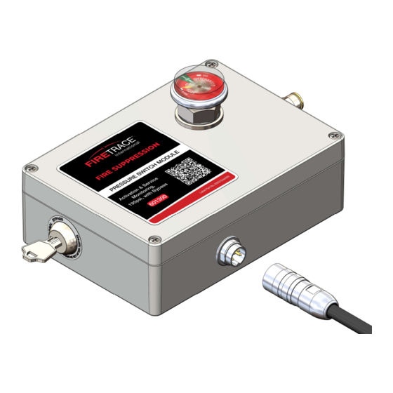
3.1.2 Standard (without Bypass)
Reference the number callouts in Figure 7 above for the process below
1.
Unscrew the four screws (1) in the corner of the box
2.
Remove cover
3.2 Configuring the Module
The Dual Pressure Switch Module utilizes a series of adjustable toggle switches on a circuit board to configure the available pressure switch and
bypass key switch states. In Figure 8, the toggle switches numbered for identification and highlight which pressure switch they are tied to. These
toggle switch numbers will be referenced in Table 2 & Table 3. The identification numbers for the toggle switches are screen-printed onto the PCB
The bypass key switch can be configured to perform distinct functions on each of the pressure switches when the key is moved to the bypass position.
DIOM 800095-A
Figure 7 – Exploded View | Standard
Figure 8 – Configuration Board Overview
5
1
7/22/2022