CALEFFI ThermoSetter 116140AC Anweisungen für Installation, Inbetriebnahme und Wartung - Seite 4
Blättern Sie online oder laden Sie pdf Anweisungen für Installation, Inbetriebnahme und Wartung für Kontrolleinheit CALEFFI ThermoSetter 116140AC herunter. CALEFFI ThermoSetter 116140AC 9 Seiten. Recirculation thermal balancing valve
Auch für CALEFFI ThermoSetter 116140AC: Handbuch (12 seiten), Anweisungen für Installation, Inbetriebnahme und Wartung (13 seiten)
1
2
1
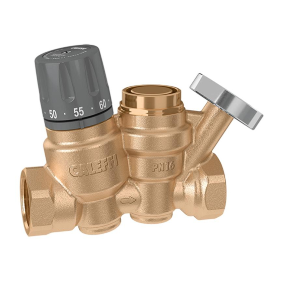
Thermostatic control,
1164xxA series
Function A
At the set temperature, the valve plug (1),
controlled by the thermostatic balancing cartridge
(2), gradually closes the outlet to the minimum
flow (3). The outlet never fully closes to always
2
allow a minimum flow for temperature sensing
and to prevent recirculation pump dead-heading.
If the temperature decreases, the outlet increases,
causing flow and thus temperature to increase
back to the set temperature as shown in curve 1. If
temperature exceeds the set-point, the plug stays
in the minimum closed position as shown in curve
2. The balancing cartridge has a throttling range of
45°F, from full open to minimum position.
Installation
Before installing the ThermoSetter, flush the pipes to make sure that impurities in system
will not interfere with valve performance. Strainers of sufficient capacity at the inlet from the
water main are highly recommended. The ThermoSetter can be installed in any position,
vertical or horizontal, following the flow direction indicated by the arrow on the valve body.
The ThermoSetter must be installed according to the diagrams given in this manual. It must
be installed to allow free access to for checking on operation and maintenance procedures.
Scan to view
·
Installation Tip
2
3
3
1
3
Thermostatic control with check valve,
11614xAC series
G (gpm)
Cv
max
(2.1)
Cv
design
(0.69)
Cv
min
(0.35)
4
T
set
T (°F)