CALEFFI 626601 Schnellstart-Handbuch - Seite 3
Blättern Sie online oder laden Sie pdf Schnellstart-Handbuch für Schalter CALEFFI 626601 herunter. CALEFFI 626601 12 Seiten. Flow switch

Per una corretta installazione occorre attenersi alle seguenti istruzioni:
Installazione
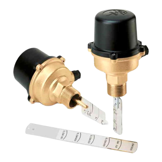
- tagliare la lamella contrassegnata con il diametro della tubazione sulla
Installation
Installation
- installare il flussostato sulla tubazione attenendosi al senso del flusso
Einbau
Instalación
Установка
- il collegamento alla tubazione può essere effettuato saldando direttamente
- l'apparecchio deve essere installato possibilmente con asta di comando in
To fit the switch correctly follow these instructions:
- cut the blade marked with the diameter of the pipe in which the switch is
- fit the flow switch to the pipe, carefully observing the direction of flow
- the tee connection in the pipe can be formed by the direct welding of a
- this also applies to a 1" diameter pipe, as the blades are designed to be
- whenever possible the equipment should be installed with control stem in
Pour une installation correcte, il est nécessaire de suivre les instructions
- choisir la languette correspondant au diamètre du tube où sera monté le
- enlever les lamelles prévues pour des tubes d'un diamètre superieur, en
- pour les diamètres supérieurs ou égaux à 3" (DN 80), il faut rajouter la
- installer le flussostat sur la canalisation en vérifiant le sens de passage du
- le raccordement à la canalisation peut être fait en soudant directe ment un
1 1/2"
DN 40
2"
DN 50
2 1/2"
- il est préférable d'installer l'appareil sur une canalisation horizontale, monté
DN 65
3"
DN 80
4"
DN 100
quale l'apparecchio va installato;
indicato dalla freccia stampigliata sul coperchio e sulla parte esterna del
corpo, ed in modo tale che la distanza tra la superficie superiore della
tubazione ed il punto di giunzione tra corpo e coperchio del flussostato
sia di 80 mm;
un manicotto filettato, anche per il diametro di 1" in quanto le lamelle sono
studiate per essere contenute in dimensioni ridotte. È tuttavia opportuno
controllare che la saldatura sia esente da bave nella sua parte interna in
modo che la lamella possa ruotare liberamente nel manicotto;
posizione verticale per evitare depositi di impurità che causerebbero il non
corretto funzionamento.
to be installed;
indicated by the arrows stamped on the cover and on the switch mounting
plate. When fitted, the distance between the upper surface of the pipe and
upper surface of the switch mountuing plate should be 80 mm;
threaded socket;
contained in these smaller dimensions. It is however advisable to check
that the weld is free from burrs on the inside so that the blade can move
freely in the tee connection;
the vertical position to avoid deposits of impurities which may cause it to
function incorrectly.
suivantes:
flussostat;
dévissant les vis de fixation;
lamelle longue, en la coupant au diamètre voulu;
fluide (indiqué par une flèche sur le couvercle et sur l'extérieur du corps) La
distance entre le tube et la jonction corps/couvercle doit être de 80 mm;
manchon fileté. Ceci dès le 1", car les lamelles sont suffisam ment étroites.
Il faut vérifier la qualité interne de la soudure du manchon sur la canalisation,
afin que la lamelle puisse manoeuvrer librement;
avec l'axe de commande à la verticale au-dessus de la canalisation, afin
d'éviter tous dépôts qui nuiraient au bon fonctionnement.
3
