702P01226
July 2013
Revision A
®
Xerox
FreeFlow
Quick Connect Guide
Base install for the Xerox® FreeFlow® Print Server on the Xerox Color 560/570 Printer.
Step 1: Connect Peripherals and Cables
1 1 1 1
2 2 2 2 A A A A
2C
2C
2C
2C
7 7 7 7 C C C C
9
9
9 9
9
9 9
9
6 6 6 6
®
1 1 1 1
Connect the power cable located in the nationalization kit to the AC receptacle located on the back of the
DFE. Connect the other end to the power strip also located in the kit.
2 2 2 2
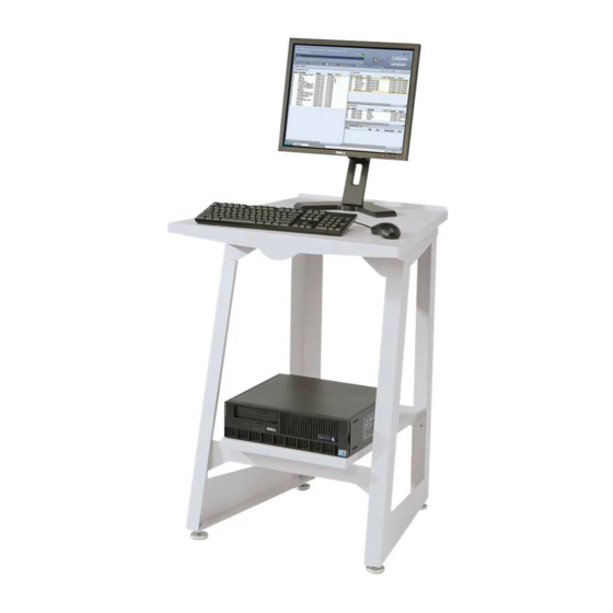
Connect the monitor cables to the DFE and the monitor.
2A. Connect one end of the VGA monitor cable to the VGA jack located on the back of the monitor.
Connect the other end to a VGA jack located on the back of the DFE.
2B.
Connect the square end of the USB upstream cable with the beveled edges to the USB jack located
underneath the monitor (not
2C.
Connect the other end of the USB upstream cable to one of the USB jacks on the back of the
3 3 3 3
Connect the Spectrophotometer cable to a USB jack on the back of the DFE.
Note: The Spectrophotometer is optional, and can also be connected to a USB jack on the front of the DFE.
4 4 4 4
Connect the keyboard to the bottom left USB jack on the back of the DFE.
5 5 5 5
Connect the mouse to the bottom right USB jack on the back of the DFE.
6 6 6 6
Connect the IOT interface cable to the Aria PWB in PCIe Slot 1. Connect the other end to the corresponding
slot on the printer.
7 7 7 7
Connect the (5 Port) Communication Ethernet Switch box to the DFE and the printer.
Remove the Communication Ethernet Switch box, its power cable, the three (3) RJ-45 ethernet cables, and
the Velcro strip from the DFE box.
Note: It is recommended that you mount the Switch box to either the back of the printer or to the back of
the stand using the Velcro strip (or one similar to the Velcro strip provided in the DFE box). It is also
3 3 3 3
recommended that you mount the box before connecting the cables in order to prevent the cables
from becoming tangled.
Note: The three RJ-45 ethernet cables are not required to be connected to the Switch box in any particular
order. The sequence for the following steps corresponds to the Switch box diagram below.
9
9 9
9
4 4 4 4
A. Connect one end of an ethernet cable (1 of 3) to the RJ-45 receptacle on the printer. Connect the other
5 5 5 5
end of the cable to the port labeled 1 on the Switch box.
B. Connect one end of an ethernet cable (2 of 3) to the external network drop on the wall. Connect the
other end to the port labeled 3 on the Switch box.
C. Connect one end of an ethernet cable (3 of 3) to the onboard network port 2 (with black surround) on
the back of the DFE. Connect the other end to the port labeled 5 on the Switch box.
D. Connect the power cable to the power source. Connect the other end of the power cable to the AC
receptacle on the back of the Switch box.
8 8 8 8
After connecting all of the cables to DFE, turn on the power button located on the power strip.
Print Server
shown).
7 7 7 7 A A A A
7 7 7 7 B B B B
To
To
To
To
To
To
To
To
Print
Printer er er er
Print
Print
Network Drop
Network Drop
Network Drop
Network Drop
7 7 7 7 D D D D
7C
7C
7C
7C
D D D D
To
To
To
To
DFE
DFE
DFE
DFE
DFE.

