Alderon Industries Versa'larm VA01A Handbuch für Betrieb, Wartung und Installation - Seite 2
Blättern Sie online oder laden Sie pdf Handbuch für Betrieb, Wartung und Installation für Sicherheitssystem Alderon Industries Versa'larm VA01A herunter. Alderon Industries Versa'larm VA01A 4 Seiten. 1 zone alarm
Auch für Alderon Industries Versa'larm VA01A: Handbuch für Betrieb, Wartung und Installation (4 seiten)

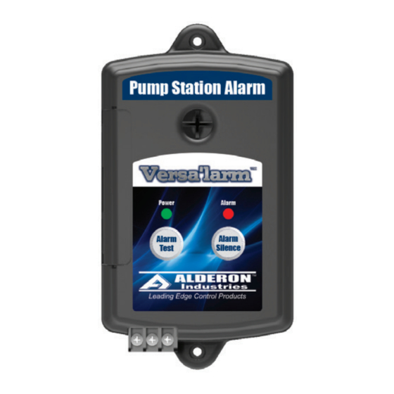
Versa'larm
1-Zone Alarm - Model VA01A
Operation, Maintenance and Installation Manual
Installation of the Alarm Panel
1. To install/replace the battery for the backup power feature, remove the access cover (Fig. 1) and install 9 VDC battery
(Duracell model MX 1604B2 / Fig. 2). After installing battery, the green power LED should illuminate, then press and hold
the "Alarm Test" pushbutton (Fig. 3) to activate the alarm and make sure the battery is working properly. The buzzer should
annunciate and the alarm LED should illuminate. If using the auxiliary contacts, leave the access cover off until step 4 is
completed. If the auxiliary contacts are not used, replace the access cover (Fig. 4).
(Fig. 1)
2. Determine the mounting location for the alarm panel. Make sure power outlet (120 VAC, 50/60 Hz) is within 5-feet of the
alarm panel (Fig. 5). The power outlet should be on a separate circuit breaker from any other device and not on a switched
receptacle to maintain power integrity. Mount the alarm panel using two #6 self-tapping screws (not included / Fig. 6). Use
two #8 plastic anchors (not included / Fig. 7) if mounting the alarm panel to sheet rock.
(Fig. 5)
5 ft. Max
3. If auxiliary contacts are not used, go to step 6. If connecting alarm to an existing system, go to Figure 9 on page 3. If using
auxiliary contacts to connect to an Auto Dialer, refer to wiring diagram below (Fig. 8). When a signaling device such as a
float switch, water or sump sensor is activated, it will close relay contacts on Terminals 1A and 1B of the alarm panel which
activate the Auto Dialer. When connected, replace the access cover and pull wire(s) through the knockout(s) on the access
cover (see step 5). CAUTION! - Route all wires away from sharp objects and internal components when installing wires.
Terminals 1 and 2
Auto Dialer Power Supply
RED = "+"
BLACK = "-"
Terminals 3 and 4
Auto Dialer Contacts
YELLOW = 1A
WHITE = 1B
Alarm Systems
Control Panels
Alderon Industries - Hawley, MN | 218.483.3034 | [email protected] | alderonind.com
™
(Fig. 2)
To Phone Line
Float Switches
(Fig. 3)
(Fig. 6)
(Fig. 8)
+ -
Leak Detection Systems
(Fig. 4)
(Fig. 7)
+
1A
1B
P/N: 101444
- 1A
1B
Page 2 of 4
