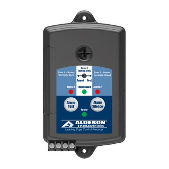
Alderon Industries Versa'larm VA02B Handbuch für Betrieb, Wartung und Installation - Seite 3
Blättern Sie online oder laden Sie pdf Handbuch für Betrieb, Wartung und Installation für Sicherheitssystem Alderon Industries Versa'larm VA02B herunter. Alderon Industries Versa'larm VA02B 4 Seiten. 2-zone alarm

Versa'larm
2-Zone Alarm - Model VA02B
Normally Open / Normally Closed
Operation, Maintenance and Installation Manual
Installation of the Alarm Panel Continued
4. After the access cover has been removed from the alarm panel (Fig. 9), use a needle nose pliers (not included) to remove
the desired "break away tabs" from the access cover, lightly pull and twist off tab(s) (Fig. 10). Replace the access cover and
run wire(s) through the knockout(s) (Fig. 11).
(Fig. 9)
5. Make note of the alarm condition(s) you are monitoring and write them on the provided label, located on the right side of
the alarm panel.
6. Connect one or more normally open sensors (rated 9 VDC, 200 mA Minimium) to Terminals C and 1. When using multiple
normally open sensors, they are wired in "parallel" (Fig. 12). Connect one or more normally closed sensors (rated 9 VDC,
200 mA Minimum) to Terminals C and 2. When using multiple normally closed sensors, they are wired in "series" (Fig. 12).
Note: When using multiple sensors, a wire nut connection may be required for all sensors connected to Terminal C and from
that wire nut connection, bring only a single 18 gauge wire to Terminal C on the alarm panel.
An optional 9-12 VDC Indoor/Outdoor LED Strobe Beacon (Alderon P/N: 7933) can be connected to Terminals C and 3.
Connect the Red Wire (+) from the LED Strobe Beacon to Terminal C on the alarm panel and connect Black Wire (-) from
the LED Strobe Beacon to Terminal 3 on the alarm panel. As required, use appropriate junction box and conduit to connect
from the alarm panel to the LED Strobe Beacon. The LED Strobe Beacon may be mounted indoor or outdoor for a remote
indication of alarm activation.
Alarm Systems
Control Panels
Alderon Industries - Hawley, MN | 218.483.3034 | [email protected] | alderonind.com
™
(Fig. 10)
ZONE 1
Normally Open
Sensors in Parallel
ZONE 2
Normally Closed
Sensors in Series
Float Switches
Leak Detection Systems
(Fig. 11)
(Fig. 12)
NOTE:
Multiple sensors can be
used on each zone
BEACON
Indoor / Outdoor
LED Strobe Beacon (alarm)
Page 3 of 4
