Alderon Industries VersAlarm 4X Handbuch für Betrieb, Wartung und Installation - Seite 2
Blättern Sie online oder laden Sie pdf Handbuch für Betrieb, Wartung und Installation für Sicherheitssystem Alderon Industries VersAlarm 4X herunter. Alderon Industries VersAlarm 4X 6 Seiten. 2-zone outdoor
Auch für Alderon Industries VersAlarm 4X: Handbuch für Betrieb, Wartung und Installation (3 seiten)

VersAlarm
2-Zone | Outdoor Alarm System, Type 4X
Operation, Maintenance and Installation Manual
Description of Operation
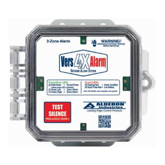
The VersAlarm™ 4X 2-Zone alarm panel with included auxiliary contacts is outdoor rated and powered by 120VAC or 240VAC
(voltage depends on model) with conduit connections (required). When powered, the green LEDs (bottom/middle) will illuminate
(solid) to indicate the alarm is powered and the included two-level press-and-hold feature can disable LEDs (see factory settings,
page 6). Install a 9VDC lithium battery for battery backup during power outages. This alarm panel can be used for a wide variety
of applications, including but not limited to: septic tanks, sump pits, holding tanks, pump chambers, and water tanks.
The alarm panel is equipped with audible and visual alarm indication, activated by a normally open or normally closed sensor wired
to the quick connect terminals for monitoring two zones. A variety of sensors can be used such as a float switch, pressure switch,
or any "dry" type sensor that "closes" during an alarm condition (normally open or normally closed). Use the auxiliary contacts to
connect to building automation systems (BAS) and phone dialers.
An alarm condition occurs when the sensor (signaling device) contact is activated for zone-1 and/or zone-2, during which the red
alarm LEDs will illuminate (flashing) with the green LED illuminated (solid) for zone-1 (left) and/or zone-2 (right) alarm indication,
buzzer will annunciate with a pulse tone, and auxiliary contacts will activate. The alarm condition will stay on until the sensor for
zone-1 and/or zone-2 is deactivated. Press and hold (1-second +) the test/silence capacitive touch button to silence the buzzer
during an alarm condition, the alarm LEDs remain illuminated, flashing. The silence condition will reset when the sensor for zone-1
and/or zone-2 deactivates and the alarm will auto reset for the next alarm cycle. Test alarm monthly to ensure system integrity,
press and hold (1-second +) the test/silence button, the red alarm LEDs should illuminate (flashing), buzzer should annunciate with
a pulse tone, and auxiliary contacts should activate.
Note: If zone-1 is in an alarm condition and the buzzer is silenced, and then zone-2 goes into an alarm condition, the buzzer will reactivate until the test/silence
capacitive touch button is pressed to acknowledge that a new alarm condition has occurred.
Battery Backup - Installation and Quick Test
1. To install or replace the battery for the backup power feature, open the alarm panel enclosure cover.
2. Install a 9VDC lithium battery (not included) matching the terminals on the alarm circuit board (Fig. 1A) to the terminals
on the top of the battery. Make sure the connection is securely fastened.
3. Test to verify proper installation of the battery, the green power LEDs (bottom/middle) will not illuminate (Fig. 2) to
conserve power. Press and hold (1-second +) the test/silence capacitive touch button to activate alarm test. The red alarm
and green power/zone indicator LEDs should illuminate in quick alternating pulses (Fig. 3), buzzer should annunciate with
four quick pulse tones matching indicators, and auxiliary contacts should activate.
Note: The LED pulse/flash functions and buzzer tone patterns are different during the testing process while on battery power versus when the incoming
power is connected. See system testing on page 5 for testing with incoming power connected and page 6 to change factory settings for disabling LEDs.
CAUTION: Do not connect incoming power to the alarm panel until all steps of the installation are complete and the system is ready for testing.
WARNING! Lithium batteries MUST be used in any installation where the temperature can drop below 32 degrees Fahrenheit. Failure to install the proper
battery type will cause battery failure at low temperatures and may not provide battery backup alarm protection.
(Fig. 1)
1A
Low Battery at 7.8 volts or Improper Installation (when powered):
The red LEDs illuminate and buzzer annunciates in sync with two quick
pulses every 10-seconds, the auxiliary contacts will remain closed.
Alarm Systems
Control Panels
Alderon Industries - Hawley, MN | 218.483.3034 | [email protected] | alderonind.com
4X
™
(Fig. 2)
Float Switches
Leak Detection Systems
(Fig. 3)
P/N: QSG00307_Rev01
Page 2 of 6
