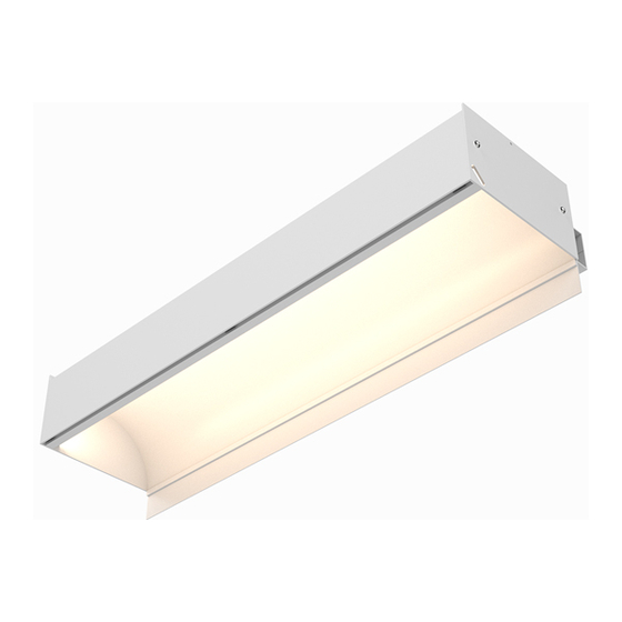
CALI alumLEDs ALS500T-RMW-HC Installationsanleitung Handbuch - Seite 4
Blättern Sie online oder laden Sie pdf Installationsanleitung Handbuch für Beleuchtungsanlagen CALI alumLEDs ALS500T-RMW-HC herunter. CALI alumLEDs ALS500T-RMW-HC 16 Seiten.
Auch für CALI alumLEDs ALS500T-RMW-HC: Installationsanleitung Handbuch (16 seiten)

1
Install concealed ceiling system grid. Assemble the grid so there is a continuous
6-15/16" opening where luminaires will be installed. The installation area must
have at least 10" of overhead space from ceiling line.
Note: Do not hang ceiling drywall before luminaires are installed. Luminaires
must be mounted prior to installation of ceiling drywall to allow top access.
Wall Stud
5/8" Drywall
2
Hang or cut drywall along installation area so it is 1/16" above ceiling line.
Measure exactly 4" above ceiling line and mark each wall stud in the installation
area. Use a laser level to ensure accurate relation to ceiling line, then draw a
reference line connecting each mark along the wall studs.
Note: Drywallers must hang drywall to the specifications. Only cut if necessary.
Mark Wall Stud
4"
Top of drywall
3
Mark locations along Wall Trim extrusion where it will be mounted to wall studs,
then drill holes as needed and mount to wall studs.
Note: Mount Wall Trim extrusion using at least 1 screw per 2', rounded up.
Mount Wall Trim
CALIFORNIA ACCENT LIGHTING, INC.
2820 E. Gretta Lane, Anaheim, CA 92806
ph. 800.921.CALI (2254) | fx. 714.535.7902 | [email protected] | calilighting.com
© CALI. All rights reserved. CALI reserves the right to make changes or withdraw specifications without prior notice.
Projected Location of
Hard Ceiling 5/8" Drywall
Ceiling Line
6-15/16"
1/16"
Ceiling Line
Ceiling Line
ALS500T-RMW-HC
Mounting (Hanging Bracket Assembly ) 1 of 2
4
Determine number of Hanging Brackets required.
Note: Refer to the diagrams on page 10 as a guide.
5
If applicable, assemble Hanging Bracket Arms. Insert Hex Head Bolts through
slots on Hanging Bracket Arms and secure with washers and hex nuts.
Slot
Lock Washer
8-32 x 2"
Hex Head Bolt
6
Mark locations where each Rail Bracket will be installed along reference line.
Align the bottom of the Rail Bracket with the reference line and pre-drill using
proper drill bit for surface and screw size. Each rail must be mounted with a
minimum of two screws. Drill additional holes in Rail Brackets if necessary.
Note: Use 8/32 x 2" Countersink Screw (By others)
Rail Bracket
Countersink Screw
7
Install Hanging Bracket Arms to luminaire by sliding inverted Hex Head Bolts of
Hanging Bracket into the channels pictured below.
Do not slide into any other channels.
8
If applicable, install end caps to ends of runs.
INSTALLATION INSTRUCTIONS
Hanging Bracket Arm
Hex Nut
5 / 20 / 2021 / Rev 3
Page 4 of 16
